Connections – Westermo EDW-100 User Manual
Page 25
25
6616-2203
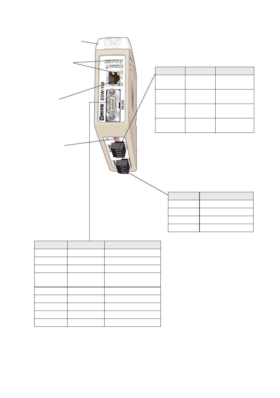
LED indicators, also
integrated in the RJ-45
connector.
(for details see next page)
S2 DIP-switch
Termination
(for details see page 25)
S1 DIP-switch under lid
(for details see page 25)
Ethernet 1
RJ-45 connection
(for details see next page)
Connections
Power connection
screw terminal
RS-232 (DTE)
* Direction relative this unit
RS-422/485 interface
screw terminal
The EDW-100 supports redundant power
connection. The positive input are +VA and
+VB, the negative input for both supplies are
COM. The power is drawn from the input
with the highest voltage.
4-position Direction* Description
No. 1
In
R+
line RS-422
No. 2
In
R–
line RS-422
No. 3
In/Out
T+
line RS-422/485
No. 4
In/Out
T–
line RS-422/485
4-position
Description
No. 1
Common
No. 2
+VA
No. 3
+VB
No. 4
Common
9-position
Direction
Description
No. 1
N/C
Not connected (DCD)
No. 2
In
Received Data (RD)
No. 3
Out
Transmitted Data (TD)
No. 4
Out
Data Terminal Ready
(DTR)
No. 5
–
Signal Ground (SG)
No. 6
In
Data Set Ready (DSR)
No. 7
Out
Request To Send (RTS)
No. 8
In
Clear To Send (CTS)
No. 9
N/C
Not connected (RI)