Led indicators – Westermo ID-90 User Manual
Page 11
11
6607-2204
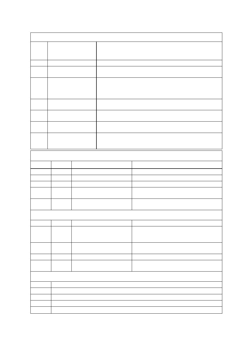
LED Indicators
Indications via LED’s:
L1ISDN Line status
LED normally showing the status of the ISDN S0 interface.
L1 together with L2 is also used to indicate error conditions
in the ID-90 and the connection to the ISDN S0 interface.
L2
ISDN Data connection
LED Normally showing the state of the data connection
ANS
Auto answer
OFF = ID-90 will reject incoming calls.
ON = ID-90 will respond to incoming calls
ANL
Analogue line
Only used when V.90 option installed.
OFF = No analogue connection established
BLINK = Analogue call in progress
ON = Analogue line established
TD
Transmit Data
LED showing data from the DTE, the LED will blink when data
received
RD
Receive Data
LED showing data transmitted to the DTE, the LED will blink
when data transmitted
RTS
Request to Send
LED showing the status of the handshake line RTS from DTE,
LED is ON when DTE requests to send data.
DCD
Data Carrier Detect
LED showing the status of the handshake line DCD from ID-90,
The behavior of the DCD-line is programable, see configuration
command cdcd.
Active states:
L1
L2
Status
Action
⊗
Θ
5x1s
Start up phase
⊗
Ο
Connection to ISDN S0 OK ; ISDN ok, no ISDN connection established
⊗
∅
Call setup in progress
⊗
⊕
Waiting for B channel
synchronization
⊗
⊗
Data connection is
established
Error states:
L1L2
Status
Ο
Ο
ID-90 NOT OK
No power or Hardware error, check
power distribution, send ID-90 for repair
if necessary
Θ
1x1s
Ο
Connection to ISDN S0
Check ISDN interface/ -connector
NOT OK
Ο
Θ
2x1s
ID-90 internal RAM error
ID-90 repair necessary
Ο
Θ
1x1s
ID-90 internal ROM error
Reload Flash firmware, repair ID-90
if necessary
LED Legend:
⊗
ON
∅
Short on, long off Cycle 1 s
⊕
Long on, short off Cycle 1 sec
Θ
Continuous blinking: n times every m seconds, (nxms)
Ο
Off