Tr ta nt id-90, Id-90 d, Gr 4 fax – Westermo ID-90 User Manual
Page 8
8
6607-2204
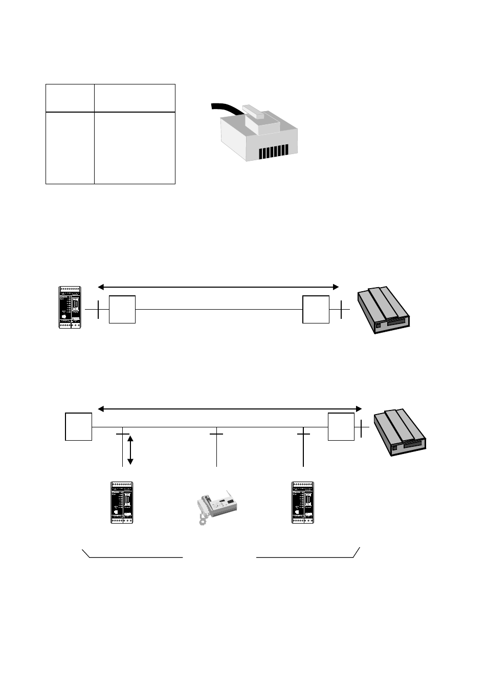
Typical S0-bus connections
The Terminal equipment TE/TA like the ID-90 Terminal adapter can be connected to the
NT in 3 different ways always with a terminating resistor TR in each end of the bus, TR
should in all three cases be 100 ohm:
• Point to Point. In this configuration the ID-90 is the only TA on the S0 bus.
A distance d1 of 1000 m is generally archived with a 0.3 mm
2
40 nF/km cable.
• Short Passive Bus. The short passive bus puts no restriction on the distance between
units, but only specifying the maximum round trip delay to be 10 to 14 µs giving a d1
of 100 to 200 m depending on the cable impedance. Up to 8 ID-90 in combination with
other terminal equipment can be connected to the S0 bus with a maximum connection
length d2 = 10 m.
1
2
3
4
5
6
7
8
9
TR
TR
TA
NT
ID-90
1
2
3
4
5
6
7
8
9
ID-90
d
2
d
1
GR 4 Fax
1
2
3
4
5
6
7
8
9
ID-90
TA
TE
NT
TA
Point to Point Configuration
Short Passive Bus
Max 8 TA/TE
TR
TR
d
1
ISDN S0 interface
The ISDN S0 interface is connected via a 8-pol RJ-45 connector.
Pin
Function
number
3
Transmit +
4
Receive
5
Receive
6
Transmit
1, 2, 7, 8
No connection
12
3456
78