5 input signal connections – Westermo RM-505U-K User Manual
Page 26
505K Radio Telemetry Module
User Manual
ELPRO Technologies Pty Ltd 2008
Page 26
will not be lost when batteries are removed, so no special
procedure is required when changing batteries.
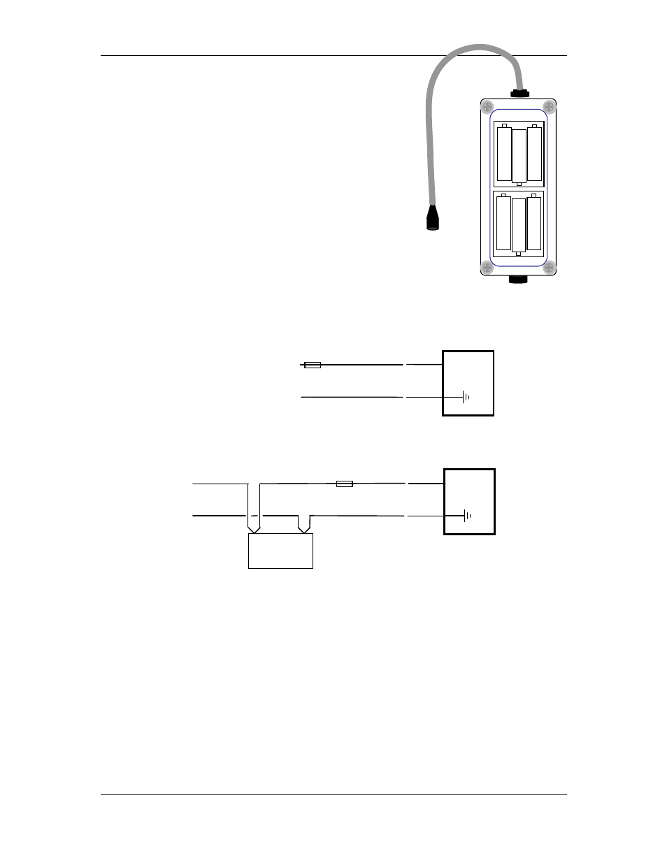
Batteries should be inserted as per the drawing - with the BU-
5-2 aligned such that the cable comes out of the top of the
module.
The BU-5-2 can be mounted in any direction. The enclosure lid
can be rotated.
3.4.2 External Power
The 505K module will accept an external supply of 6 - 30 volts
DC. An external supply with a battery and battery charger is
suitable. Negatively grounded or floating supplies are
acceptable, however positively grounded supplies must not
be connected. The 505K connects the negative supply
(COMMON) to “ground”. Connect the external supply as per
the following diagram.
⊂
⊂
+
-
5.4 - 30 VDC
505U
EXT
SUPPLY
GND
1 amp
⊂
⊂
+
-
BATTERY
CHARGER
505U
EXT
SUPPLY
GND
1 amp
12V
BATTERY
3.5 Input Signal Connections
3.5.1 Digital/Pulse Inputs
Digital and pulse inputs share the same input channel. Each input is connected between the
DIN connector and COMMON. Inputs can be voltage-free contacts, NPN transistor
switches, or a TTL voltage signal (ON < 1.5 volt DC, OFF > 3.5 volts DC).