Westermo RM-505U-K User Manual
Page 27
man_505U-K_1.4.doc
Dec 2008
ELPRO Technologies Pty Ltd 2008
Page 27
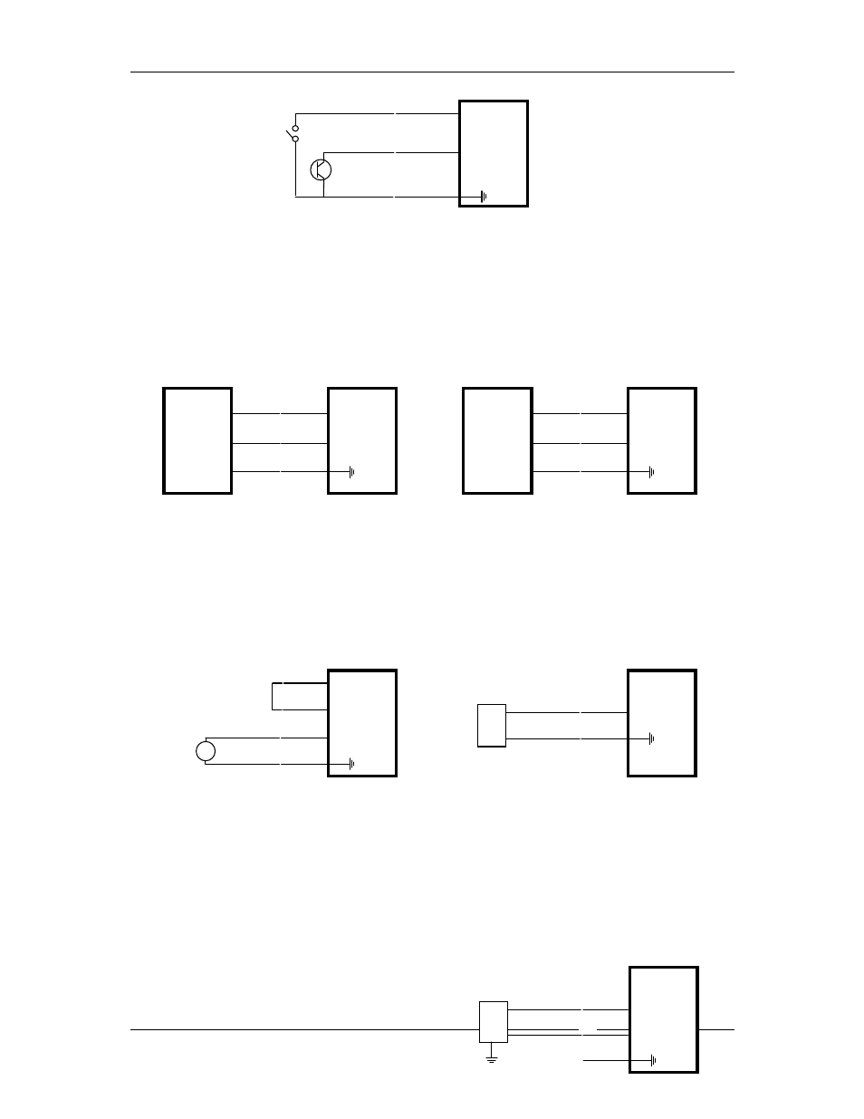
⊂
GND
505U-K
DIN1
⊂
⊂
DIN2
Inputs can be voltage free contact or
open-collector transistor
NPN
Inputs do not have any surge protection. If the sensor or switch is mounted a long way from
the 505K module, external isolation such as a relay may be required for surge protection.
3.5.2 Shaft Encoder Connections
⊂
⊂
⊂
COUNT
DIRECTION
GND
DIN2
DIN1
505U-K
⊂
⊂
⊂
PHASE 1
PHASE 2
GND
DIN2
DIN1
505U-K
INCREMENTAL SHAFT ENCODER
QUADRATURE SHAFT ENCODER
3.5.3 Analogue input
The analogue input has a positive and a negative terminal, and may be placed at any point in
the current loop, as long as neither input rises more than 27V above COMMON or ground.
An internal DC/DC converter provides 24 VDC 50mA supply for powering analogue loops .
⊂
⊂
GND
AI-
505U-K
⊂
⊂
+
-
AI+
505U-K
⊂
LOOP POWERED TRANSDUCER
EXTERNALLY POWERED TRANSDUCER
⊂
⊂
⊂
+
-
AI+
AI-
ANALOG
SUPPLY
Shielded cable is recommended for analogue input loops to minimise induced noise and radio
frequency interference (RFI). The shield of the cable must be connected to earth at one end of
the cable only. Each input has a loop resistance of 150
Ω
and zener diode protection against
overvoltage and reverse voltage. Additional surge protection is recommended in high
electrical noise environments, or if the analogue signal cable runs for a long distance
underground before connecting to the 505K
module.
Voltage Input
Voltage inputs are connected to the AI+ and
⊂
+
-
AI+
505U-K
⊂
VOLTAGE INPUT
AI-
⊂
⊂
GND