Westermo RM-505U-K User Manual
Page 44
505K Radio Telemetry Module
User Manual
ELPRO Technologies Pty Ltd 2008
Page 44
The 505K will be calibrated for a 4-20mA
signal in the factory. You can calibrate for
a different input signal.
1. If you are using a voltage signal, first
set the internal “jumpers” as per section
3.5.3
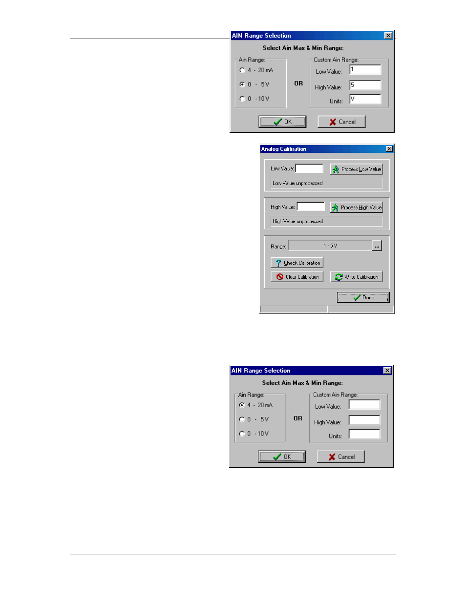
2. Select the “AIN Calibration” box on the
main display. The “AIN Range
Selection” box will display.
3. If you wish to calibrate to 4-20mA, 0-5V or 0-
10V, simply select the range on the left side of
the box. If you want another range, enter the
low and high values and units on the right side
of the box - for example, for 1 – 5 volts, you
would enter 1, 5 and V.
If you enter a range on the right side, the left side
is ignored. When you have entered the range,
select “OK”.
4. The “Analogue Calibration” display will appear.
This display allows you to enter user calibration
values into the 505K. First, you can check any
existing user calibration figures by selecting
“Check Calibration” - if there is any existing
calibration figures, these will appear.
5. To calibrate the analogue input, connect the analogue signal to the 505K. Adjust the
signal to the minimum value (0%). Select “Process Low Value” - the calibration value
for this signal will appear.
6. Now adjust the signal to the maximum
value (100%). Select “Process High
Value”.
7. When you have finished this process,
select “Write Configuration” - this will
write the configuration values to the
user-calibration registers in the 505K.
Select “Done” and the analogue signal
is calibrated.
The accuracy of the analogue signal can
only be as accurate as the calibration. For
high accuracy measurement, you will need to use a high accuracy mA or V meter to ensure
that the high and low values are correct.
If you wish to return to the factory-calibration, select “4-20mA” at the AIN Range Selection
display, then “Clear Calibration” at the “Analogue Calibration” display.