Westermo RM-505U-K User Manual
Page 36
505K Radio Telemetry Module
User Manual
ELPRO Technologies Pty Ltd 2008
Page 36
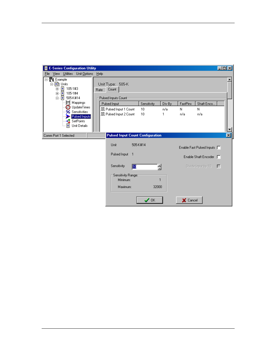
4.7 Pulse Inputs
Each 505K has two pulse inputs. Each pulse input has 2 x 16 bit counters and a calculated
pulse rate value. The 2 x 16 bit counters are a base counter which increments on each pulse,
and an “HI” counter which increments each time the base counter overflows. Either or both
counters can be transmitted, although each is transmitted individually.
There are several
configurable parameters for
pulse inputs. The paralysis
value can be adjusted from
the Unit Details selection,
as per Digital Inputs.
The pulse inputs also have a
Sensitivity value. The pulse
input sensitivity is the
number of pulse increments
since the last transmission to
trigger another transmission. For example, if the pulse count at the last transmission for a
pulse input was 1000, and the sensitivity value is 10, then another transmission will occur
when the pulse count reaches 1010 (provided there has not been an update transmission
during this period). The sensitivity values can be between 1 and 32000.
If either pulse input has an input rate of more than 10Hz, then the Fast Pulse Input option
should be selected from the Pulsed Inputs selection. This is selected at “Pulse Input 1 Count”
even if you are using PI2. That is, if either PI1 or PI2 is faster than 10Hz, select “Enable Fast
Pulse Inputs” for PI1. Selecting Fast PI will increase the power consumption of the 505K and
is not suitable for battery supplies.
PI2 has a user-configurable divider for scaling its pulse counters. PI1 does not have a divider.
The PI2 divider can be an integer from 1 – 255. If the divider is set to X, then the base
counter will increment by 1 for every X input pulses.