1 i/o mapping – Westermo RM-505U-K User Manual
Page 31
Advertising
man_505U-K_1.4.doc
Dec 2008
ELPRO Technologies Pty Ltd 2008
Page 31
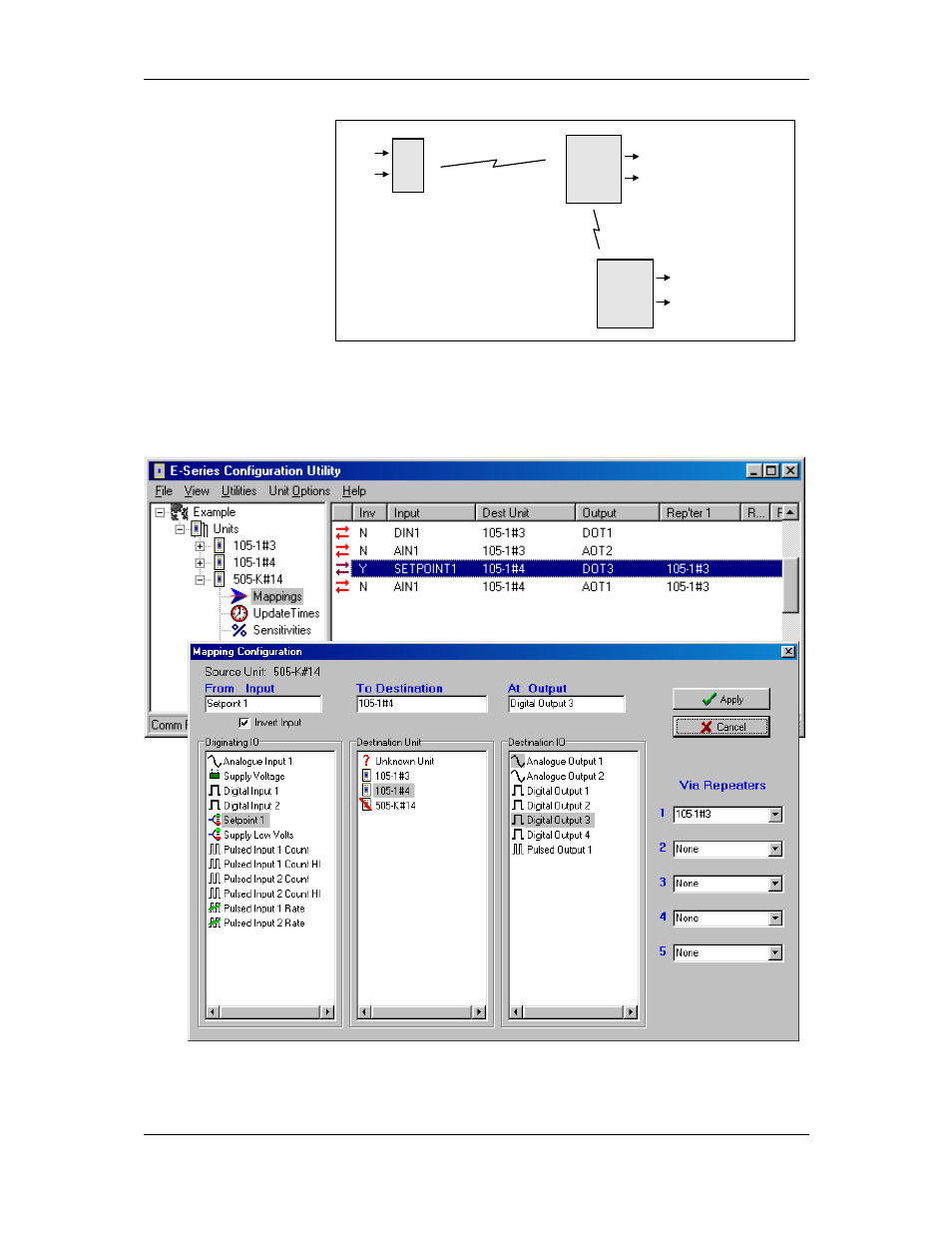
4.1 I/O Mapping
Enter I/O mappings as
per the 105U manual.
In
the
following
example, a digital input
at a 505K is mapped to
DO1 of 105U#13. The
analogue input of the
505K is mapped to AO2
of the same module.
The setpoint status of the 505K is mapped (inverted) to DO3 of 105U#14, using 105U#13 as
a repeater. The 505K AI is also mapped to AO1 of this module. That is, the AI is mapped
twice.
The mapping configuration for the 505K would be :
4.2
505U
105U
105U
#14
#3
#4
DIN1
AIN
DO1 (DIN1 from #14)
AO2 (AIN from #14)
AO1 (AIN from #14)
DO3 (SP inv from #14)
Advertising