2 assembling the motor base plate, 3 attaching the drive parts, 4 installing the infeed hopper – AEC Colortronic MSH Series 2039 User Manual
Page 14
C Series Granulators
Installation
14 of 53
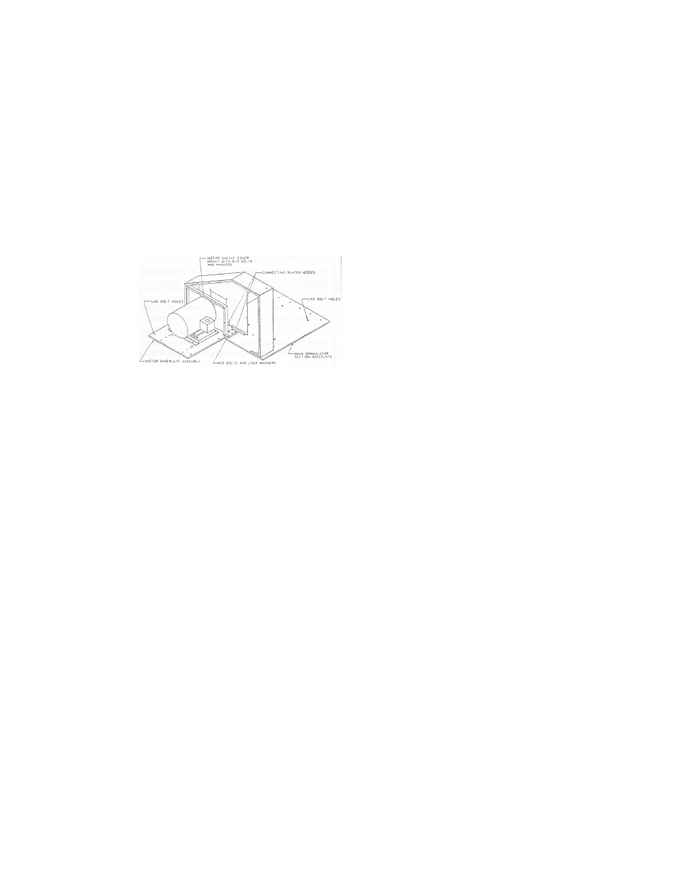
3-2 Assembling the Motor Base Plate
Use the following procedure to assemble the motor base plate:
1. Move the motor base plate into position, as shown in Figure 2.
2. Use the two connecting plates (part number 53253) with the hardware supplied to
fasten the two base plates.
3. Check that the motor base plate is level and resting firmly on the floor.
4. Lag the motor base plate to the floor through the holes provided.
Note: Vibration isolation pads may be used between the base plate and the floor.
Figure 2: Motor Base Plate
3-3 Attaching the Drive Parts
Use the following procedure to attach the drive parts:
1. Attach the motor sheave cover with the hardware supplied.
2. Slip the belts into the grooves, one at a time, making sure that the motor base has
been adjusted enough to allow the belts to be installed without danger of
overstressing them by forcing them over the edges of the V-grooves.
3. Tension the drive belts as instructed in Section 5-10 on page 35.
Note: Belt drives should initially be tensioned at the “run-in” recommended force.
Check the tension at least twice during the first two days of operation. After the
belts have seated themselves in the sheave grooves and the initial stretch is
removed, re-tension the belts to “normal running” and check periodically to
maintain tension at the recommended value.
4. Fasten the guard cover over the drive.
3-4 Installing the Infeed Hopper
When installing the infeed hopper, check the weight of the hopper and make sure to size the
hoist and accessories accordingly. Use the following procedure to install the hopper:
1. Thread two 3/4-16 UNF eyebolts into the two tapped blocks at the top of the hopper.
2. Run strapping or chains of appropriate lifting capacity to the eyebolts.
3. Use a hoist of appropriate capacity to lift the hopper into position.
4. Fasten the hopper to the upper cutting chamber using the hardware supplied.