ARAG Bravo 300s series computers crop spraying - Direct connection - INSTALLATION User Manual
Page 11
Advertising
11
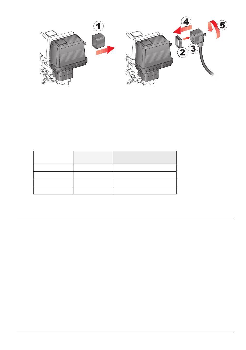
Fix the connectors to the relevant valves according to the initials indicated in your assembly general
diagram (Par. 6.1 - System recommended composition).
• Remove the protection cap (
1, Fig. 10) from the electric valve.
• Place the seal (
2) onto the connector (3) and push the connector fully on (4): be careful not to
bend the contacts upon insertion on the valve.
• Tighten the screw (
5) fully home.
If the number of monitor switches is greater than the number of section valves, con-
nect cables as specified in Table 2.
NO. OF
SECTION VALVES
SWITCHES
TO BE USED
CABLES TO BE CONNECTED
TO SECTION VALVES
2
2 - 4
2 - 4
3
2 - 3 - 4
2 - 3 - 4
4
1 - 2 - 4 - 5
1 - 2 - 4 - 5
6
1 - 2 - 3 - 4 - 5 - 6
1 - 2 - 3 - 4 - 5 - 6
Tab. 2
CONTINUeS
Advertising
This manual is related to the following products: