4 rear panel connections – ARM Electronics DVRHD User Manual
Page 10
DVR User’s Manual
9
Connecting Short-term Device
If any short-term devices shall be installed to the DVR as parts of the unit
system, such as USB ThumbDrive® or any USB devices, etc, make sure
those devices are connected only after the unit is powered up. The reason is
because the DVR can recognize the external devices only after the power-up
process is done completely.
2.4
Rear Panel Connections
There are various connectors on the rear panel for the DVR installations. The
following figure shows the connectors by name; and followed by the detailed
description of each connector.
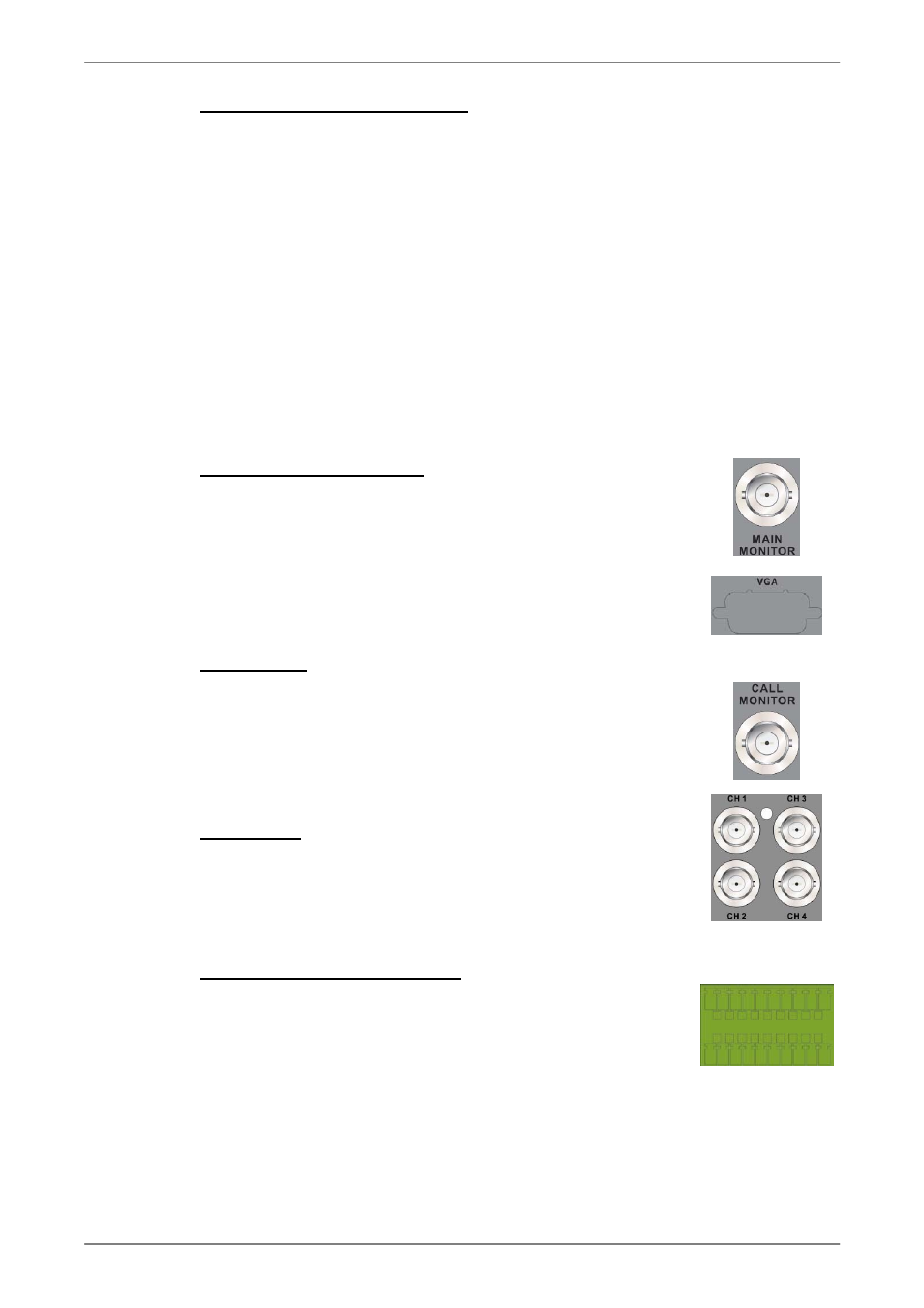
Main Monitor (BNC/ VGA)
BNC and VGA output connectors are offered for
connecting to a main monitor. The main monitor displays
live image and playback recorded video in either
full-screen or split-window format. VGA output connector is
optional.
Call Monitor
The call monitor is used to display full screen video of all
installed cameras in sequence. The BNC call monitor
connector allows users to connect the DVR with an
optional call monitor.
Video Input
A group of BNC connectors is offered for video input
streams from installed cameras. The number of connectors
is equal to the number of channels.
Alarm I/O & RS485 & Audio In
Terminal block connectors are provided to offer users the
flexibility to connect the DVR to Alarm I/O, RS-485, and
Audio In devices. The definition of pins varies for different
models. Refer to Setup Guide for detailed pin definitions.