Back panel, Power, External i/o – ARM Electronics ENDVR9A User Manual
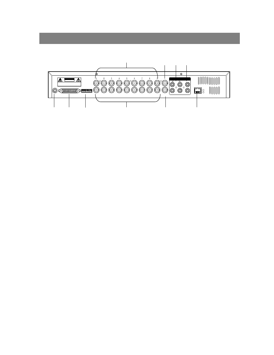
Page 9: 75ω / hi, Video input (1-9), Call, Audio out (r/l), Audio in (1-4), Main, Loop (1-9)
5
1. POWER
Please use the provided adaptor to connect power cord (Other adaptor is not suitable for this machine).
2. EXTERNAL I/O
•
Controlled remotely by an external device or control system.
•
Alarm input, external I / O explanation.
3. 75Ω / HI
When using Loop function, please switch to HI. If you don’t use Loop function or disconnect the video
input, please set it as 75Ω.
4. VIDEO INPUT (1-9)
Connect to video source, such as camera.
5. CALL
Connect to CALL monitor. Show the Switch Display. When alarm trigger happens, the call monitor will show
the triggered channel for a period of time.
6. AUDIO OUT (R/L)
Connect to monitor or speaker.
•
IPS should be set to 25A (for NTSC) or 18A (for PAL
)
✻ with 2 mono audio outputs from the same source.
7. AUDIO IN (1-4)
Connect to audio source, such as microphone.
•
IPS should be set to 25A (for NTSC) or 18A (for PAL)
✻ 4 audio inputs, but only can select 1 during recording.
8. MAIN
Connect to Main monitor
9. LOOP (1-9)
Connect video signal between Input port and Loop port to make a loop.
10. LAN
Connect DMR by network.
BACK PANEL
EXTERNAL I/O
POWER
75Ω
2
CALL
LOOP
INPUT
R ISK OF ELE CTR IC SHOC K
D O N OT OPEN
WARNING : TO R ED UCE THE R ISK OF ELEC TRIC SHOCK,
D O NOT REMOVE C OVER (OR BACK).
NO USER-SERVIC EABLE PARTS IN SIDE.
REFER SERVICING TO QUALIFIED
SERVICE PERSONNEL.
HI
1
MAIN
ACT
L
4
LINK
R
3
OUT
IN
LAN
①
②
③
④
⑤
⑥
⑦
⑧
⑨
⑩