Multicast flow, Working mechanism – H3C Technologies H3C S12500 Series Switches User Manual
Page 13
6
3.
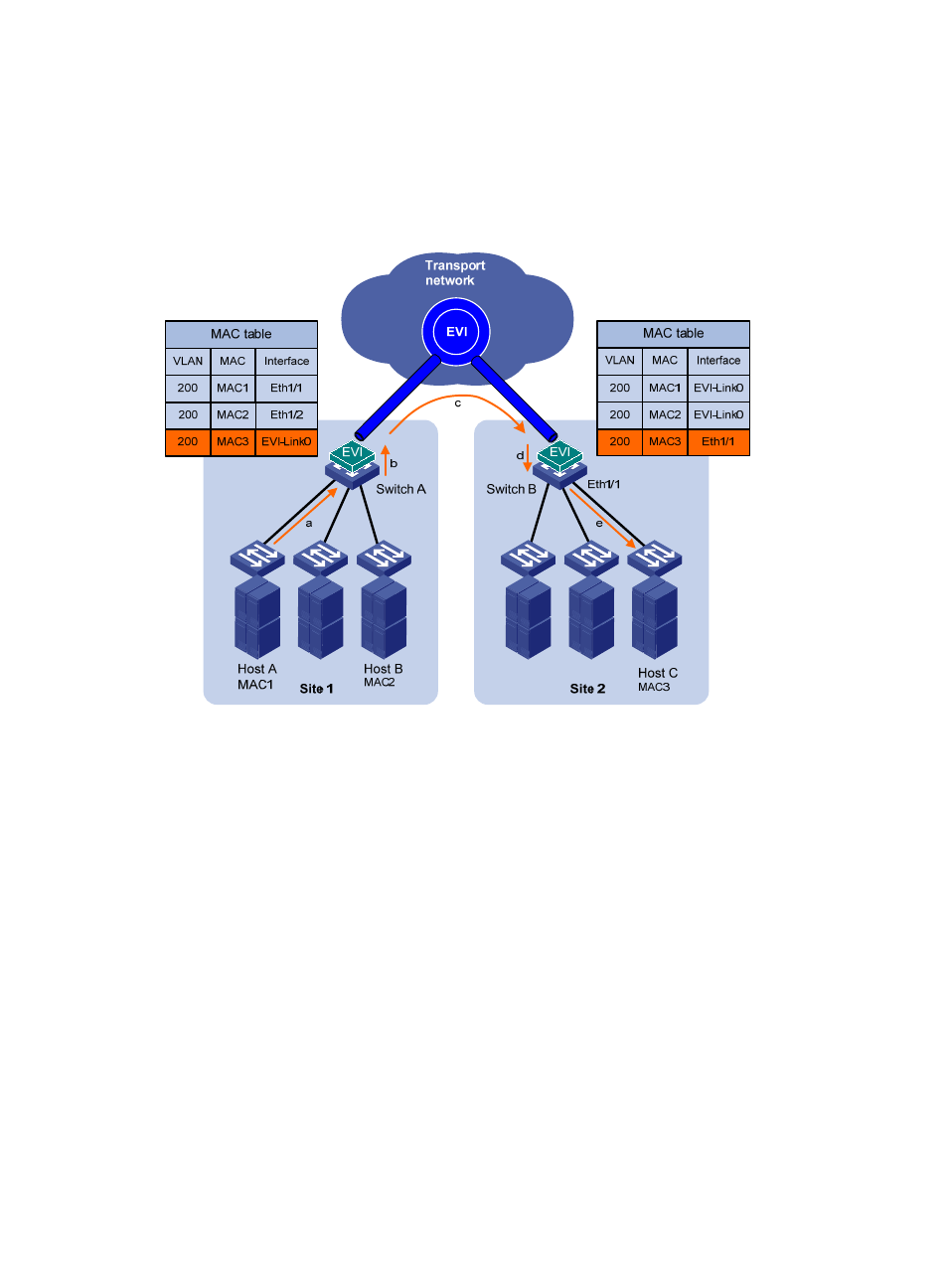
The source edge device forwards the encapsulated packet out of the EVI link to the destination
edge device across the IP transport network.
4.
The destination edge device removes the headers of the original Ethernet frame, looks up the
destination MAC address in the MAC address table, and sends the frame out of the matching
outgoing interface.
Figure 5 Layer 2 forwarding between sites
Multicast flow
Edge devices run IPv4 IGMP snooping or IPv6 MLD snooping on each extended VLAN and learn
multicast router port and multicast member port information on EVI-Link interfaces for Layer 2 multicast
forwarding as if they were Ethernet interfaces. In an extended VLAN, each edge device tunnels IGMP,
MLD, and PIM protocol packets to all its remote edge devices, and the remote edge devices flood the
packets in the VLAN.
For a site-to-site multicast data frame in an extended VLAN, the following process (see
) takes
place:
1.
The DR in a site sends out a multicast frame.
2.
The source edge device copies the frame and encapsulates one copy on each multicast member
EVI-Link interface.
3.
The source edge device unicasts the encapsulated frames to the destination edge devices over the
EVI links.
4.
Each destination edge device removes the headers of the multicast frame and copies the multicast
frame on each multicast member interface.
5.
Each destination edge device sends the multicast frame out of all member interfaces to the
destination hosts.