Single-homed evi network configuration example, Network requirements, Configuration procedure – H3C Technologies H3C S12500 Series Switches User Manual
Page 28
21
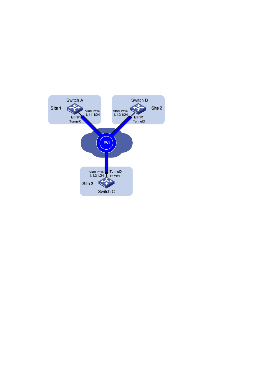
Single-homed EVI network configuration example
Network requirements
As shown in
, use EVI to connect site 1, site 2, and site 3 across an IP network into a large Layer
2 network, and extend VLAN 21 to VLAN 100 across the sites.
Use network ID 1 to identify the EVI network.
Use Switch A as an ENDS and all other edge switches as ENDCs for neighbor discovery.
Figure 8 Network diagram
Configuration procedure
This example assumes that routes have been configured for the sites to reach each other.
1.
Configure Switch A:
# Configure the EVI tunnel source interface (VLAN-interface 10 in this example), and assign the
transport-facing physical interface GigabitEthernet 3/0/1 to the VLAN.
<SwitchA> system-view
[SwitchA] vlan 10
[SwitchA-vlan10] port gigabitethernet 3/0/1
[SwitchA-vlan10] quit
[SwitchA] interface vlan-interface 10
[SwitchA-Vlan-interface10] ip address 1.1.1.1 24
[SwitchA-Vlan-interface10] quit
# Create an IPv4 EVI tunnel interface.
[SwitchA] interface tunnel 0 mode evi
# Set the network ID of the EVI tunnel interface to 1.
[SwitchA-Tunnel0] evi network-id 1
# Specify the IP address of VLAN-interface 10 as the source IP of the EVI tunnel.
[SwitchA-Tunnel0] source 1.1.1.1
# Set the tunnel keepalive interval to 20 seconds and the maximum number of transmissions to 2.
[SwitchA-Tunnel0] keepalive 20 2