Configuration procedure, Evi configuration examples – H3C Technologies H3C S12500 Series Switches User Manual
Page 36
29
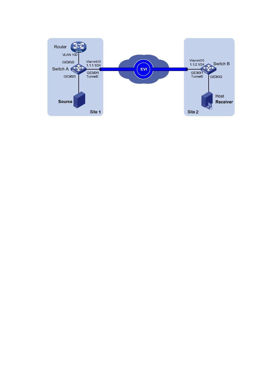
Figure 10 Network diagram
Configuration procedure
This example assumes that routes have been configured for the sites to reach each other.
1.
Configure the Router:
# Enable IP multicast routing, and enable IGMP on VLAN-interface 100.
<Router> system-view
[Router] multicast routing-enable
[Router] vlan 100
[Router-vlan100] quit
[Router] interface vlan-interface 100
[Router-Vlan-interface100] ip address 100.100.1.1 24
[Router-Vlan-interface100] igmp enable
2.
Configure Switch A:
# Configure the EVI tunnel source interface (VLAN-interface 10 in this example), and assign the
transport-facing physical interface GigabitEthernet 3/0/1 to the VLAN.
<SwitchA> system-view
[SwitchA] vlan 10
[SwitchA-vlan10] port gigabitethernet 3/0/1
[SwitchA-vlan10] quit
[SwitchA] interface vlan-interface 10
[SwitchA-Vlan-interface10] ip address 1.1.1.1 24
[SwitchA-Vlan-interface10] quit
# Create an IPv4 EVI tunnel interface.
[SwitchA] interface tunnel 0 mode evi
# Set the network ID of the EVI tunnel interface to 1.
[SwitchA-Tunnel0] evi network-id 1
# Specify the IP address of VLAN-interface 10 as the source IP of the EVI tunnel.
[SwitchA-Tunnel0] source 1.1.1.1
# Specify extended VLANs on the EVI tunnel interface.
[SwitchA-Tunnel0] evi-isis extend-vlan 21 to 100
# Configure Switch A as an ENDS on the EVI tunnel interface.
[SwitchA-Tunnel0] evi neighbor-discovery server enable