Mpls te using rsvp-te configuration example, Network requirements, Configuration procedure – H3C Technologies H3C S10500 Series Switches User Manual
Page 140
129
total statics-cr-lsp : 1
Name FEC I/O Label I/O If State
Tunnel0 -/- 30/NULL Vlan2/- Up
NOTE:
On an MPLS TE tunnel configured using a static CR-LSP, traffic is forwarded directly based on label at the
transit nodes and egress node. Therefore, it is normal that the FEC field in the sample output is empty on
Switch B and Switch C.
7.
Create a static route for routing MPLS TE tunnel traffic.
[SwitchA] ip route-static 3.2.1.2 24 tunnel 0 preference 1
Perform the display ip routing-table command on Switch A. You can see a static route entry with interface
Tunnel 0 as the outgoing interface.
MPLS TE using RSVP-TE configuration example
Network requirements
Switch A, Switch B, Switch C, and Switch D are running IS-IS and all of them are Level-2 devices.
Use RSVP-TE to create a TE tunnel with 2000 kbps of bandwidth from Switch A to Switch D, ensuring that
the maximum bandwidth of each link that the tunnel traverses is 10000 kbps.
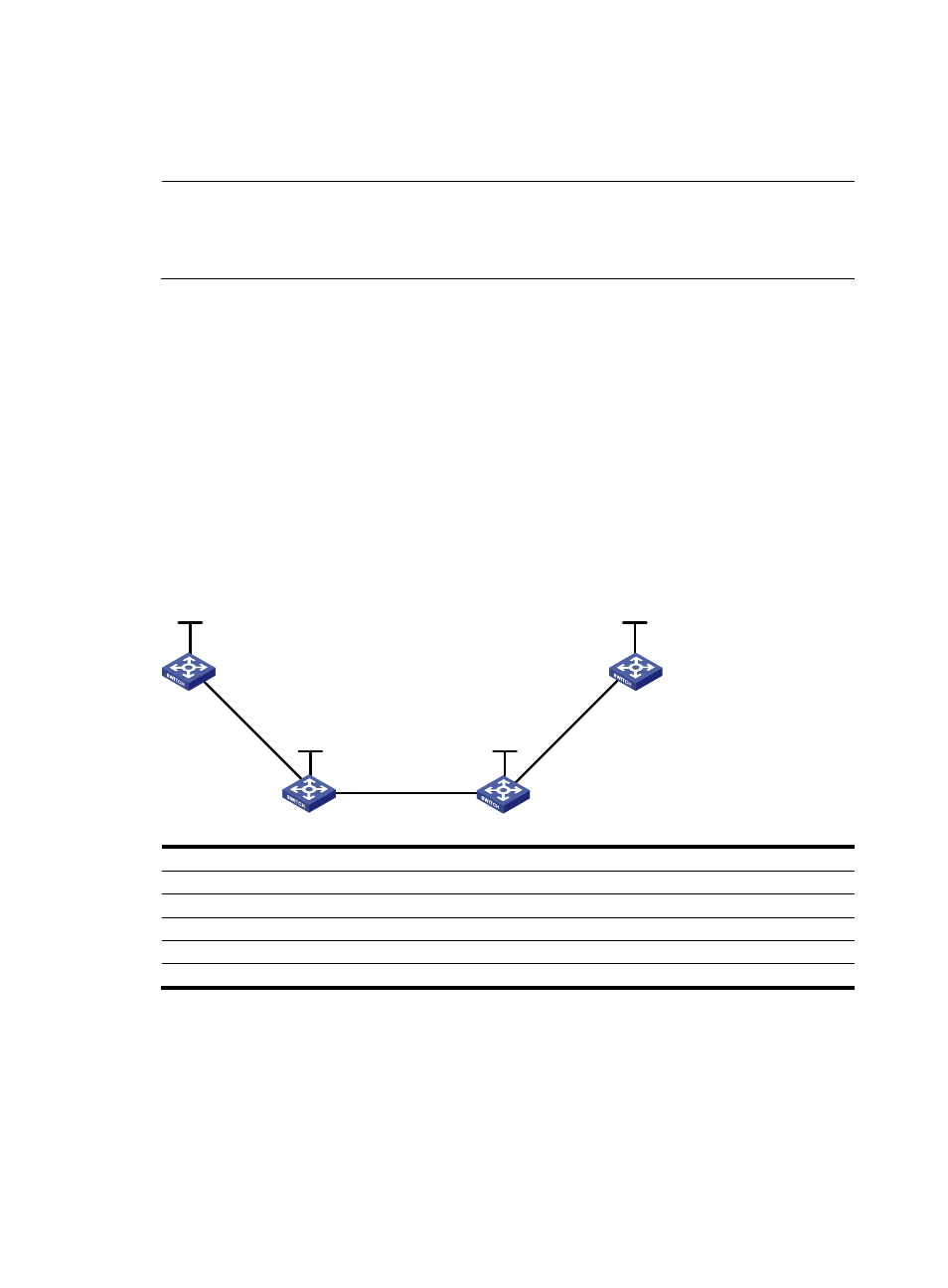
Figure 32 Set up MPLS TE tunnels using RSVP-TE
Vlan-int1
Vlan-int1
Vlan-int2
Vlan-int2
Vlan-int3
Vlan-int3
Loop0
Loop0
Loop0
Loop0
Switch A
Switch B
Switch C
Switch D
Device
Interface
IP address
Device
Interface
IP address
Switch A
Loop0
1.1.1.9/32
Switch D
Loop0
4.4.4.9/32
Vlan-int1
10.1.1.1/24
Vlan-int3
30.1.1.2/24
Switch B
Loop0
2.2.2.9/32
Switch C
Loop0
3.3.3.9/32
Vlan-int1
10.1.1.2/24
Vlan-int3
30.1.1.1/24
Vlan-int2
20.1.1.1/24
Vlan-int2
20.1.1.2/24
Configuration procedure
1.
Assign IP addresses and masks to interfaces (see
) (details not shown)
2.
Enable IS-IS to advertise host routes with LSR IDs as destinations
# Configure Switch A.
<SwitchA> system-view
[SwitchA] isis 1
[SwitchA-isis-1] network-entity 00.0005.0000.0000.0001.00