Configuration procedure – H3C Technologies H3C S10500 Series Switches User Manual
Page 325
314
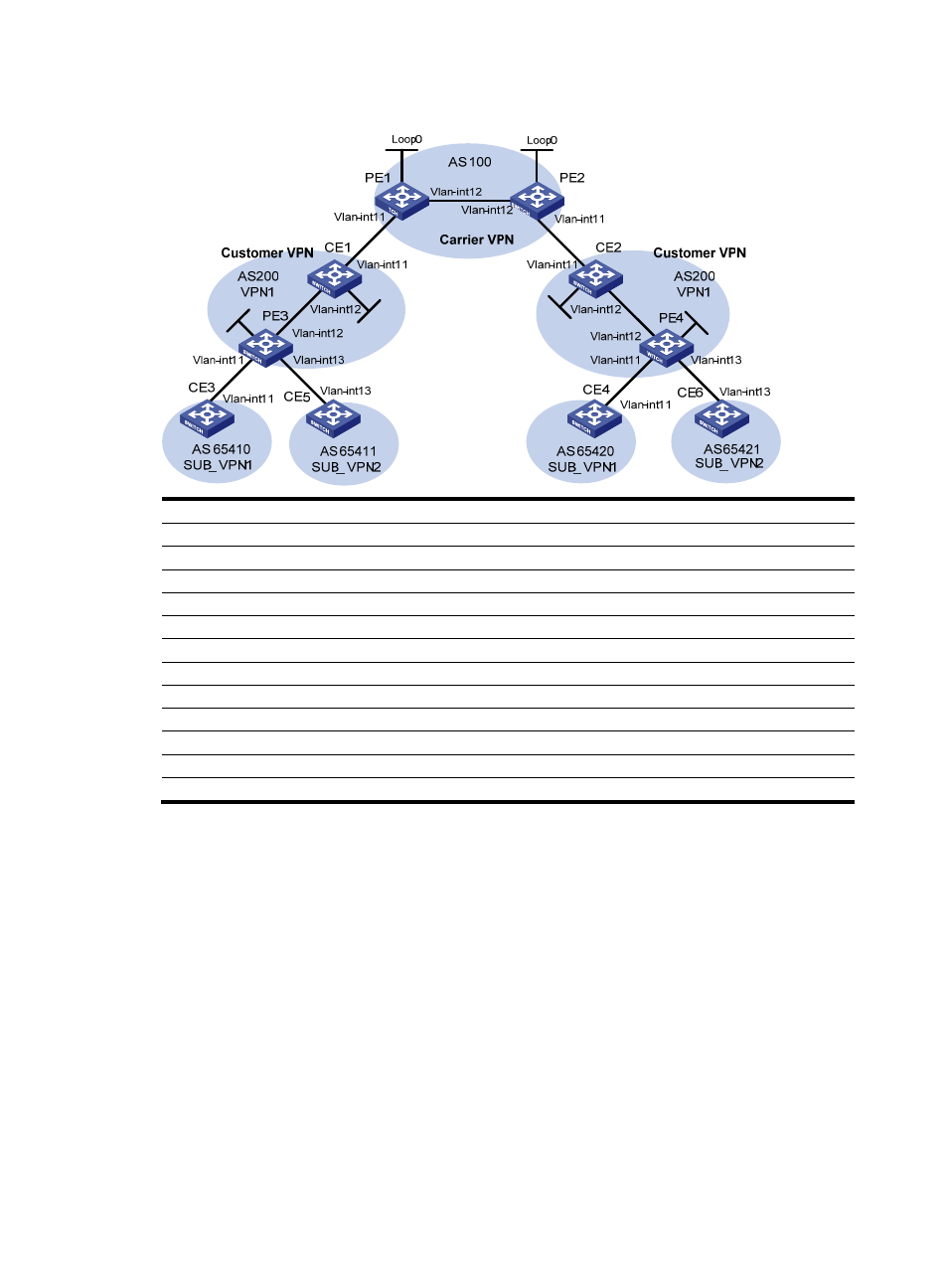
Figure 78 Configure nested VPN
Loop
0
Lo
op0
Lo
op0
Lo
op0
Device Interface IP
address
Device Interface IP
address
CE 1
Loop0
2.2.2.9/32
CE 2
Loop0
5.5.5.9/32
Vlan-int12 10.1.1.2/24
Vlan-int11 21.1.1.2/24
Vlan-int11 11.1.1.1/24
Vlan-int12 20.1.1.1/24
CE 3
Vlan-int11
100.1.1.1/24
CE 4
Vlan-int11
120.1.1.1/24
CE 5
Vlan-int13
110.1.1.1/24
CE 6
Vlan-int13
130.1.1.1/24
PE 1
Loop0
3.3.3.9/32
PE 2
Loop0
4.4.4.9/32
Vlan-int11 11.1.1.2/24
Vlan-int11 21.1.1.1/24
Vlan-int12 30.1.1.1/24
Vlan-int12 30.1.1.2/24
PE 3
Loop0
1.1.1.9/32
PE 4
Loop0
6.6.6.9/32
Vlan-int11 100.1.1.2/24
Vlan-int11 120.1.1.2/24
Vlan-int12 10.1.1.1/24
Vlan-int12 20.1.1.2/24
Vlan-int13 110.1.1.2/24
Vlan-int13 130.1.1.2/24
Configuration procedure
1.
Configure MPLS L3VPN on the service provider backbone, using IS-IS as the IGP protocol, and
enabling LDP and establishing MP-iBGP peer relationship between PE 1 and PE 2.
# Configure PE 1.
<PE1> system-view
[PE1] interface loopback 0
[PE1-LoopBack0] ip address 3.3.3.9 32
[PE1-LoopBack0] quit
[PE1] mpls lsr-id 3.3.3.9
[PE1] mpls
[PE1-mpls] quit
[PE1] mpls ldp
[PE1-mpls-ldp] quit
[PE1] isis 1
[PE1-isis-1] network-entity 10.0000.0000.0000.0004.00