Inter-as option b – H3C Technologies H3C S10500 Series Switches User Manual
Page 241
230
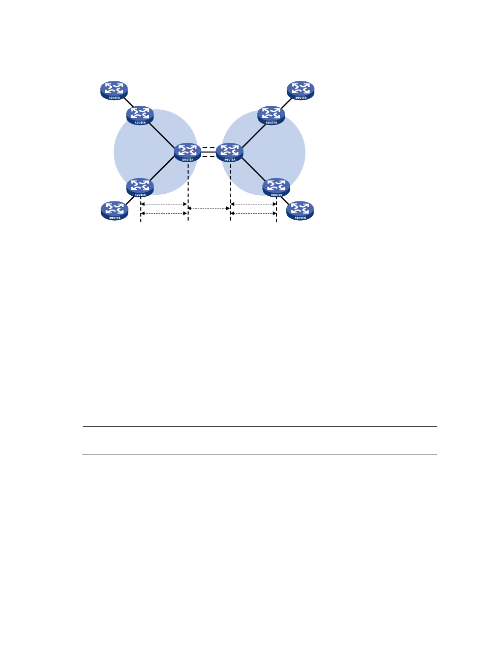
Figure 59 Network diagram for inter-AS option A
VPN 1
CE 1
PE 1
PE 3
VPN 1
CE 3
CE 2
VPN 2
VPN 2
PE 2
PE 4
ASBR 1
(PE)
ASBR 2
(PE)
VPN LSP 1
VPN LSP 2
LSP 1
LSP 2
CE 4
IP Forwarding
EBGP
AS 100
AS 200
Inter-AS option A is easy to carry out because no special configuration is required on the PEs acting as
the ASBRs.
However, it has limited scalability because the PEs acting as the ASBRs must manage all the VPN routes
and create VPN instances on a per-VPN basis. This leads to excessive VPN-IPv4 routes on the PEs.
Inter-AS option B
In this kind of solution, two ASBRs use MP-eBGP to exchange labeled VPN-IPv4 routes that they have
obtained from the PEs in their respective ASs.
As shown in
, the routes are advertised through the following steps:
1.
PEs in AS 100 advertise labeled VPN-IPv4 routes to the ASBR PE of AS 100 or the route reflector
(RR) for the ASBR PE through MP-iBGP.
2.
The ASBR PE advertises labeled VPN-IPv4 routes to the ASBR PE of AS 200 through MP-eBGP.
3.
The ASBR PE of AS 200 advertises labeled VPN-IPv4 routes to PEs in AS 200 or to the RR for the
PEs through MP-iBGP.
NOTE:
For information about RR, see
Layer 3—IP Routing Configuration Guide.
The ASBRs must perform the special processing on the labeled VPN-IPv4 routes, which is also called
ASBR extension method.