Rsvp-te gr configuration example, Network requirements, Configuration procedure – H3C Technologies H3C S10500 Series Switches User Manual
Page 146
135
RSVP-TE GR configuration example
Network requirements
•
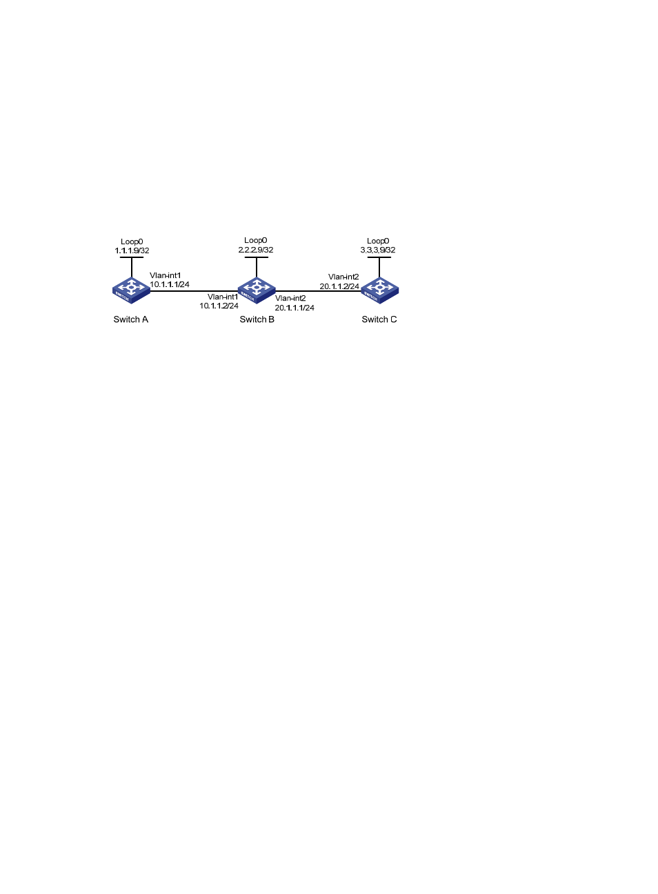
Switch A, Switch B and Switch C are running IS-IS. All of them are Level-2 devices and support RSVP
hello extension.
•
Use RSVP-TE to create a TE tunnel from Switch A to Switch C.
•
Switch A, Switch B and Switch C are RSVP-TE neighbors. With GR capability, each of them can
provide GR helper support when another is GR restarting.
Figure 33 Configure RSVP-TE GR
Configuration procedure
1.
Assign IP addresses and masks to interfaces (see
) (details not shown)
2.
Enable IS-IS to advertise host routes with LSR IDs as destinations (details not shown)
3.
Configure basic MPLS TE, and enable RSVP-TE and RSVP hello extension
# Configure Switch A.
<SwitchA> system-view
[SwitchA] mpls lsr-id 1.1.1.9
[SwitchA] mpls
[SwitchA-mpls] mpls te
[SwitchA-mpls] mpls rsvp-te
[SwitchA-mpls] mpls rsvp-te hello
[SwitchA-mpls] interface vlan-interface 1
[SwitchA-Vlan-interface1] mpls
[SwitchA-Vlan-interface1] mpls te
[SwitchA-Vlan-interface1] mpls rsvp-te
[SwitchA-Vlan-interface1] mpls rsvp-te hello
[SwitchA-Vlan-interface1] quit
# Configure Switch B.
<SwitchB> system-view
[SwitchB] mpls lsr-id 2.2.2.9
[SwitchB] mpls
[SwitchB-mpls] mpls te
[SwitchB-mpls] mpls rsvp-te
[SwitchB-mpls] mpls rsvp-te hello
[SwitchB-mpls] interface vlan-interface 1
[SwitchB-Vlan-interface1] mpls
[SwitchB-Vlan-interface1] mpls te
[SwitchB-Vlan-interface1] mpls rsvp-te
[SwitchB-Vlan-interface1] mpls rsvp-te hello