Operation indicator leds – Grass Valley 8921DAC User Manual
Page 13
8921DAC Instruction Manual
13
Power Up
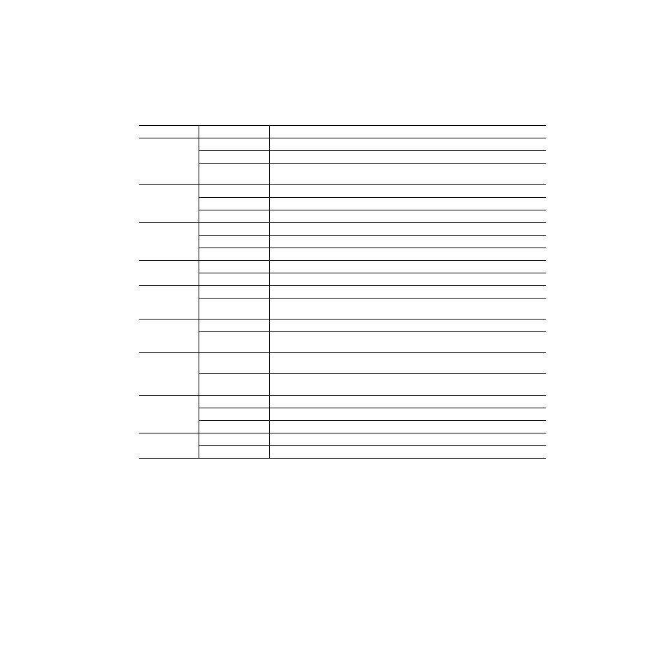
Operation Indicator LEDs
for the name and meaning of each
of the board edge operating indicators on the module circuit board.
Table 2. Board Edge LED Names and Meaning
LED
Indication
Condition
FAULT
(red)
Off
Normal operation.
On continuously
Module has detected an internal fault. (Refer to
Long Flash
User configuration problems. Input missing or not locked. Processor failed to load/configure or diag-
nostics failed on one or more devices.
COMM
(yellow)
Off
No activity on frame communication bus.
3 Quick Pulses
Locate Module command received by the module from a remote control system.
Short flash
Activity present on the frame communication bus.
CONFIG
(yellow)
Off
Module is in normal operating mode.
On continuously
Module is initializing, changing operating modes or programming hardware.
3 Quick Pulses
Locate Module command received by the module from a remote control system.
PWR
(green)
Off
No power to module or module’s DC/DC converter failed.
On continuously
Normal operation, module is powered.
ERR AES1
(red)
On
No error detected for AES 1 A/B input. SRC A/B ready.
Off
One of the following errors detected for AES 1 A/B input: CRC, Input not present, PLL AES receiver not
locked, Validity Bit set, Non-audio bit set, excessive parity error.
ERR AES2
(red)
On
No error detected for AES 2 C/D input. SRC C/D ready.
Off
One of the following errors detected for AES 2 C/D input: CRC, Input not present, PLL AES receiver not
locked, Validity Bit set, Non-audio bit set, excessive parity error.
CH SEL 1–4
(green)
Off
Indicated input A-D is not selected for AES output channel selected with CONTROL rotary switch or
audio channel 1-4 (after pairing) is not affected by adjustment selected with CONTROL rotary switch.
On
Indicated input A-D is selected for AES output channel selected with CONTROL rotary switch or audio
channel 1-4 (after pairing) is affected by adjustment selected with CONTROL rotary switch.
CH 1-4
AUDIO LVL
(green or red)
Off
Channel 1-4 Digital processed audio (before DAC) level < – 40 dBFS
Red
Channel 1-4 Digital processed audio (before DAC) level > – 40 dBFS but < – 0.5 dBFS
Green
Channel 1-4 Digital processed audio (before DAC) level > – 0.5 dBFS
BANK 2
(yellow)
Off
Bank 1 of Control rotary switch is active.
On
Bank 2 of Control rotary switch is active.