Local onboard module configuration, Configuration switches and controls – Grass Valley 8921DAC User Manual
Page 19
8921DAC Instruction Manual
19
Configuration
Local Onboard Module Configuration
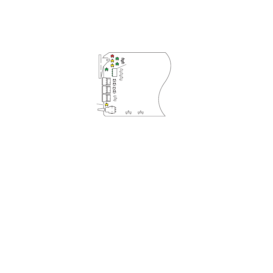
The 8921DAC module can be configured and operated locally using the
rotary and paddle switches on the front edge of the module (
).
Figure 6. Module Jumpers and Switches for Local Configuration
Configuration Switches and Controls
The switches available for local configuration are described below. Refer to
for the following descriptions:
•
MODE and CONTROL (rotary) switches — Three rotary hex switches
are present on the front edge of the module, AA (Analog Audio)
1/2 MODE, AA 2 MODE, and CONTROL.
The AA 1 and AA 2 MODE rotary switches select the output mode for
each analog audio pair from output processing settings. Local settings
for each output mode are given in
.
The CONTROL switch is used to set the available module parameters
in conjunction with the CONTROL paddle switch. It addresses two
banks of functions; each bank has 16 possible positions (0 through 9 and
A through F). Not all positions are used. The next bank of functions is
accessed each time the CONTROL switch makes a complete revolution
past zero (or back through F). While in Bank 1, a complete revolution
past zero accesses Bank 2; while in Bank 2, a complete revolution past
zero accesses Bank 1 again. The yellow BANK 2 LED indicates which
bank is currently being accessed.
Note
The CONTROL rotary switch should be kept in position 0 in any bank (parked)
when not in use to avoid any inadvertent change in configuration. Position 0
in each bank is inactive.
AA 1/2 Mode Switch
AA 3/4 Mode Switch
CONTROL Switch
BANK 2 LED
Paddle Swtich
Channel select
8214_05
1
2
3
4
S1
S2
S3