064815 dac board, 064815 dac board -36, Check status indicators -4 – Grass Valley 1200 Installation User Manual
Page 110: Figure 3-19, Dac board block diagram -36
3-36
Section 3 Ñ Functional Description
064815 DAC Board
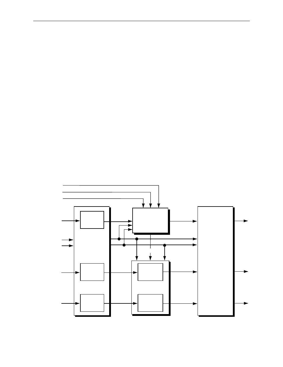
The DAC board (Figure 3-19) receives an 8:8:8 digital video signal from the
DAC Support board and converts the signal to component analog video.
The converted signal drives the 75 ohm analog outputs at the back of the
switcher frame.
Y, R-Y, and B-Y channels of the digital signal to be converted enter the DAC
board and feed three parallel digital to analog converters, U2, U9, and U14.
These converters change the video into analog, and associated passive
components provide low pass filtering of the signals as well as gain and
equalization adjustments. Jumpers associated with the DAC ICs allow the
user to select the appropriate setup and signal levels for the desired analog
format.
The analog components enter clamp circuits, such as U7, U8, and U3 for the
Y channel, where the signals are clamped to ground during back porch.
Output drivers U12, U17, and U5 and associated components scale the
analog video components to produce color difference or RGB outputs for
driving the analog BNC connectors on the back of the frame. Jumpers J5, J6,
J8, and J10 select the scaling components to be used, thereby determining
whether the output will be color difference (jumper position A) or RGB
(jumper position B). The analog output signal passes to the BNC outputs
via the DAC Support board, the Mixer module, and the rear motherboard.
Figure 3-19. DAC Board Block Diagram
Y D-A
Converter
and Filter
R-Y D-A
Converter
and Filter
B-Y D-A
Converter
and Filter
R-Y All-Pass
and
Clamp
B-Y All-Pass
and
Clamp
Sync In
Setup In
Clamp
VPlus
VMinus
Digital Y In
Digital R-Y In
Digital B-Y In
Y All-Pass, Clamp,
and Sync-Setup
Insertion
RGB Matrix
and
Output Drivers
Y Clamped
R-Y Clamped
B-Y Clamped
G/Y
R/R-Y
B/B-Y
VPlus
VMinus
Clamp