Figure 4-5, Lever arm adjustment diagnostic menu -11, Figure 4-5. lever arm adjustment diagnostic menu – Grass Valley 1200 Installation User Manual
Page 126
4-12
Section 4 Ñ Maintenance
3. The diagnostic menu will immediately appear on the screen. Enter the
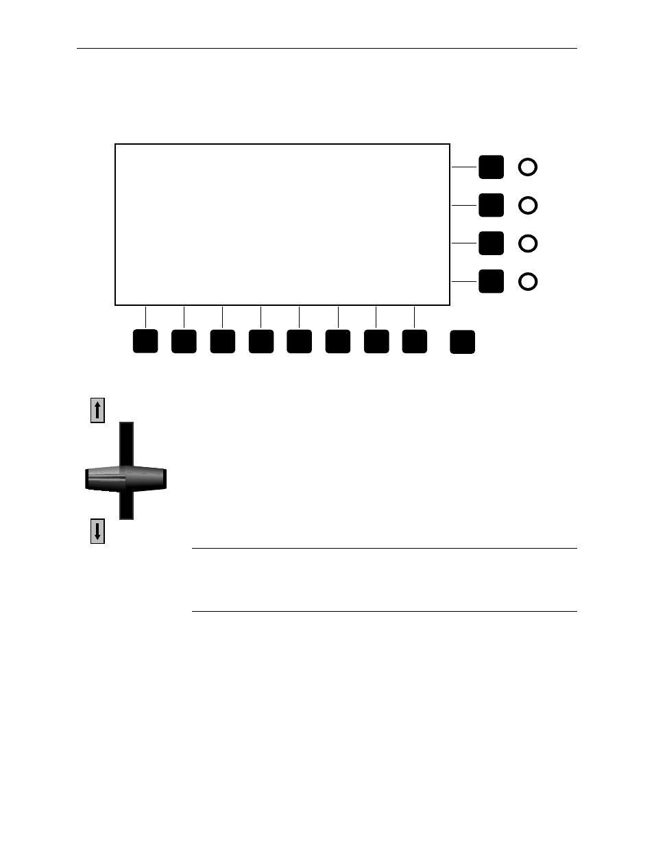
letter C using the keyboard to access the Leverarm and Joystick test
menu (see Figure 4-5).
Figure 4-5. Lever Arm Adjustment Diagnostic Menu
4. Move the lever arm on the front of the control panel to the lower edge
of the slot.
5. Adjust the R604 and R605 pots until the menu display shows
approximately 2EA (Hexcode) under the Avg column.
6. Move the lever arm to the upper edge of the slot.
7. Adjust the R604 and R605 pots until the menu display shows
approximately D20 (Hexcode) under the Avg column.
NOTE:
The R604 and R605 pots interact with each other. It may be necessary to
repeat the adjustments until the Avg reads approximately 2EA when the lever arm
is in the lower edge position and D20 when the lever arm is in the upper edge
position.
8. Turn the rotary switch, on the I/O board, to the 0 position for normal
operation.
9. Reboot the control panel using the On/Off switch.
10. Use the R604 and R605 pots to fine adjust the lever arm arrows to
extinguish approximately 1/8Ó from the lower and upper edges.
Exit
Testing leverarms and joysticks . . .
Press any key to stop the test . . .
JoyLever
Raw—Lever—2 sec—
ID
Raw
Filt
Min
Max
Avg
JoyX
####
####^
####
####
--####
JoyY
####
####v
####
####
|-####
JoyZ
####
####^
####
####
--####
MeTr
####
####v
####
####
|-####
(Lower Edge)
(Upper Edge)