Fuses, Power supply cooling, Module slots and rear connectors – Grass Valley NV8288 v.1.5 User Manual
Page 17: Nv8288, Fuses power supply cooling, Introduction
NV8288 and NV8288-Plus Digital Video Routers • User’s Guide
7
2. Introduction
Module Slots and Rear Connectors
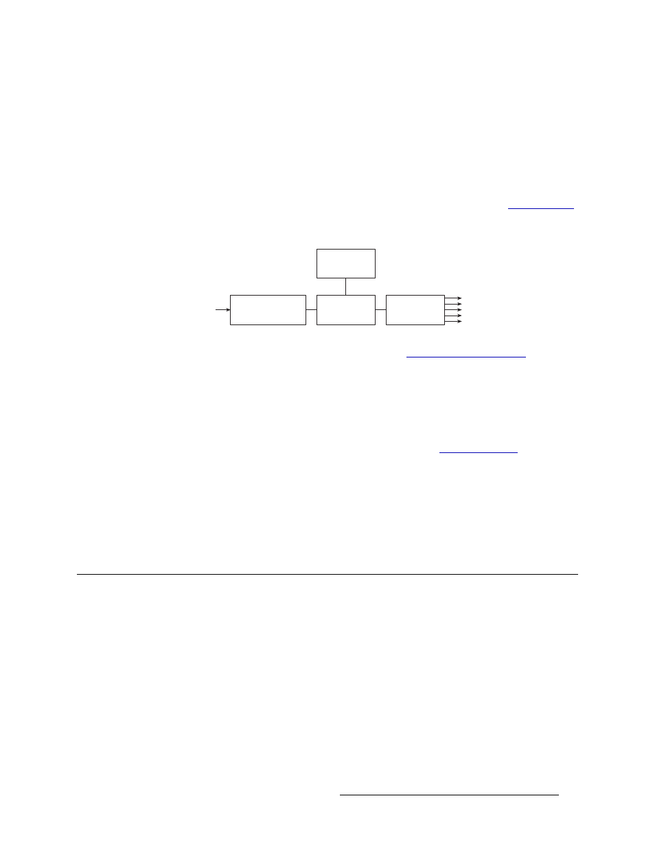
The PS6000 and PS8010 power supply modules accepts a wide range of AC input voltages and
produces five +48 VDC outputs. The power supply automatically senses the AC input voltage (90–
130 and 180–250 VAC) and adjusts to maintain a relatively constant DC output; no voltage selec-
tion is required.
The five regulated outputs are directed to modules in the router where on-board regulators produce
the DC voltages required by the local circuits. Each +48 VDC output powers one of the five green
LEDs and output test points located on the front of the PS6000 and PS8010 power supply modules.
Under normal operation, all five LEDs are lit. For more information on LEDs, see
Figure 2-3 shows the PS6000 and the PS8010 power supply module architecture.
Figure 2-3. Power Supply Module Diagram
For information on making power supply connections, see
Fuses
Fuses for AC power inputs are located on the PS6000 power supply modules. When an NV6257 is
ordered, fuses appropriate for line voltage in use at the country of destination are installed on the
PS6000 power supply modules. Be sure to check the fuse ratings for compliance with specific
requirements in your area. For information on replacing fuses, see
The PS8010 power supply module has no serviceable fuses.
Power Supply Cooling
There are four low-speed fans located along the front edge of each PS6000 and PS8010 power sup-
ply module. They are intended to pull a small quantity of air across the internal heat sinks.
Module Slots and Rear Connectors
The NV8288 and the NV8288-Plus share common hardware features. Both provide slots for hous-
ing input, output, monitor, control and crosspoint cards. Similarly, both feature non-interchangeable
backplanes that house connectors for incoming and outgoing signals. Both also share common sys-
tem connections. However, the NV8288-Plus has unique output cards and output signal connec-
tions that enable two NV8288-Plus routers to be connected together to create a system capable of
managing 576 inputs and 576 outputs.
NV8288
Figure 2-4, next page, shows the front of the NV8288 with the door removed. From this view—in
the slots that do not have an active card installed—the backside of installed backplanes and the
motherboard connectors are visible. The router features 36 upper bay slots and 36 lower bay slots
Power Sense
and Limiting
AC Input, Fuse,
Rectifiers, and Filter
Power Factor
Correction
+48VDC
Regulators (×5)
+48VDC
Out (×5)
90130VAC or
180250VAC In