Monitor expansion connections, Installation – Grass Valley NV8288 v.1.5 User Manual
Page 55
NV8288 and NV8288-Plus Digital Video Routers • User’s Guide
45
3. Installation
Making Monitor Connections
How to Make Monitor Connections
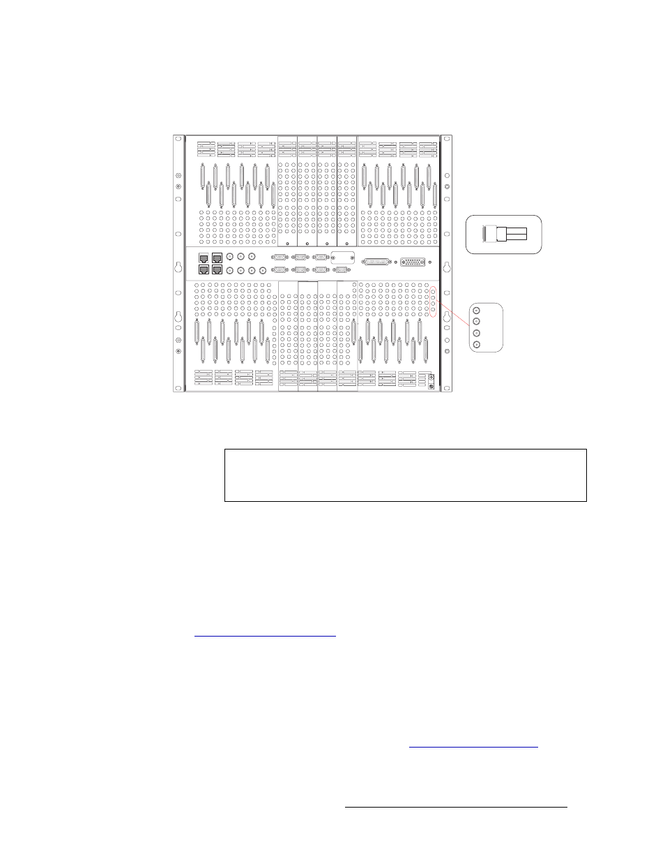
1 Locate the monitor connections on the rear of the router, as shown in Figure 3-19.
Figure 3-19. Monitor Connections and DIN 1.0/2.3 Connectors (Rear View) on the NV8288-Plus
2 Connect to the ‘OUT 1’ monitor connection using a DIN 1.0/2.3 connector and 1855A Belden
cable, or an equivalent.
3 Connect the other end of the cable to the monitoring equipment being used to monitor outgoing
signals.
4 Connect to the ‘OUT 2’ monitor connection using a DIN 1.0/2.3 connector and 1855A Belden
cable, or an equivalent.
5 Connect the other end of the cable to the monitoring equipment being used to monitor outgoing
signals.
6 If connecting two NV8288-Plus routers together, connect the monitor expansion connections.
Monitor Expansion Connections
The monitor connections are housed on a backplane containing 4 DIN 1.0/2.3 connectors. If two
NV8288-Plus routers are connected together, additional monitor expansion connections between
the routers must be connected. One router acts as the primary router. This is the router that is
directly connected to the monitoring equipment. The secondary, connected router is connected to
the primary router’s monitor expansion connections. (See
page 44.) This enables the monitoring of outgoing signals for both routers through the primary
IN 1
IN 2
OUT 1
OUT 2
Monitor connections
Mini-DIN 1.0/2.3 Connector
Note
There are several DIN 1.0/2.3 connectors and cables
suitable for use with the
router
. For a complete list of connectors and cables, contact Technical Support. For con-
tact information, see