A “y” cable. (see, Installation – Grass Valley NV8288 v.1.5 User Manual
Page 39
NV8288 and NV8288-Plus Digital Video Routers • User’s Guide
29
3. Installation
Making Power Connections
How to Connect a Single NV6257 to Two NV8288-Plus Frames
1 Locate the power cords, PS6000 power supply modules, and cables.
2 Fabricate a monitor “Y” cable. For instructions, see
3 Facing the rear of the NV6257, connect one end of the power supply cable (WC0085) to ‘Out-
put Power 2’, as shown in Figure 3-1 on page 27.
4 Facing the rear of the first router (router 1), connect the other end of the power supply cable to
‘Power Input’, as shown in Figure 3-2 on page 27.
5 Facing the rear of the NV6257, connect one end of a second power supply cable (WC0085) to
‘Output Power 1’, as shown in Figure 3-1 on page 27.
6 Facing the rear of the second router (router 2), connect the other end of the power supply cable
to ‘Power Input’, as shown in Figure 3-2 on page 27.
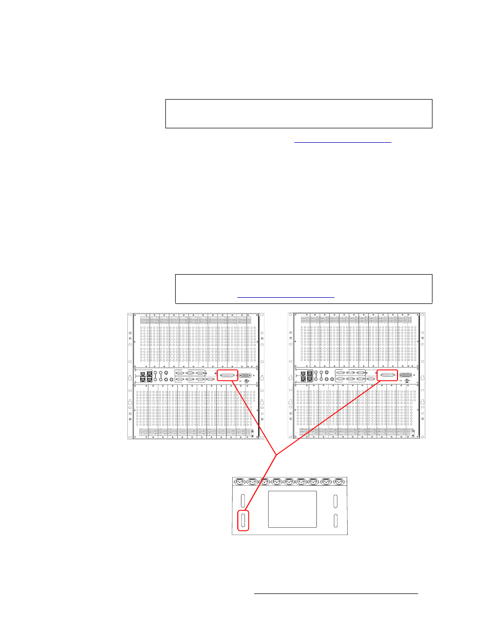
7 Facing the rear of the NV6257, connect one end of the monitor “Y” cable to ‘Power Supply
Monitors’, as shown in Figure 3-4.
Figure 3-4. “Y” Cable Connections Between Two Routers and a Single NV6257
8 Facing the rear of the first router (router 1), connect one of the two remaining monitor “Y”
cable connectors to ‘Power Supply Monitor’, as shown in Figure 3-4.
Note
Because your are connecting two routers, you will need two WC0085 power
supply cables.
Important
For steps 7, 8 and 9, be sure to use the connector wired for the connection you
are making. (See
RTR EXPANSION
E146905
10/100 BT
10/100 BT
RTR EXPANSION
VIDEO
REF 1
LOOP
VIDEO
REF 2
LOOP
AUX 1
AUX 2
CTRL 1
CTRL 1
CTRL 2
CTRL 2
ALARMS
POWER SUPPLY
MONITORS
POWER INPUT
TIME
CODE
PRI
CTRL
SEC
CTRL
PRI CTRL
SEC CTRL
DIAG (38.4 Kbaud)
DIAG (38.4 Kbaud)
RTR EXPANSION
E146905
10/100 BT
10/100 BT
RTR EXPANSION
VIDEO
REF 1
LOOP
VIDEO
REF 2
LOOP
AUX 1
AUX 2
CTRL 1
CTRL 1
CTRL 2
CTRL 2
ALARMS
POWER SUPPLY
MONITORS
POWER INPUT
TIME
CODE
PRI
CTRL
SEC
CTRL
PRI CTRL
SEC CTRL
DIAG (38.4 Kbaud)
DIAG (38.4 Kbaud)
FAN
Output
Power 1
Output
Power 2
Power
Supply
Monitors
Alarms
A “Y” cable has 3 DB25 connectors, one on each
end, creating a “Y.”
Connect one DB25 to the power supply
monitor connection on each router and the
other end to the power supply monitor
connection of the NV6257.
Router 1
Router 1
Router 2
NV6257