Making video reference connections, Making video reference, Connections – Grass Valley NV8288 v.1.5 User Manual
Page 53: Making video, Reference connections, Installation
NV8288 and NV8288-Plus Digital Video Routers • User’s Guide
43
3. Installation
Making Video Reference Connections
The following lists the DE9 pin connectors for RS-422:
3 Connect the other end of the cable to the PC running the UniConfig application.
Making Video Reference Connections
The NV8288 and the NV8288-Plus provide timing reference connections for analog video signals,
labeled ‘VIDEO REF 1’ and ‘VIDEO REF 2’. The control card uses these references to perform
takes at the proper point in time (per SMPTE RP168), determining the router’s video frame switch
points. The video reference connections require a stable source of PAL, NTSC or Tri-level sync.
Both video reference connections use 75
ohm BNC connectors and coaxial cable. For a detailed
description of the video reference connections, see
Each ‘VIDEO REF’ connection can be use the same reference source (redundant) or two unique
reference sources (dual). For more information, see
If a video reference is present, signals switch at the defined frame and line switch points. If a video
reference is not present, the router still performs takes using an internally generated reference sig-
nal. If a video reference is not connected, the control card displays a lit red LED. (See
How to Make Connections to the Video References
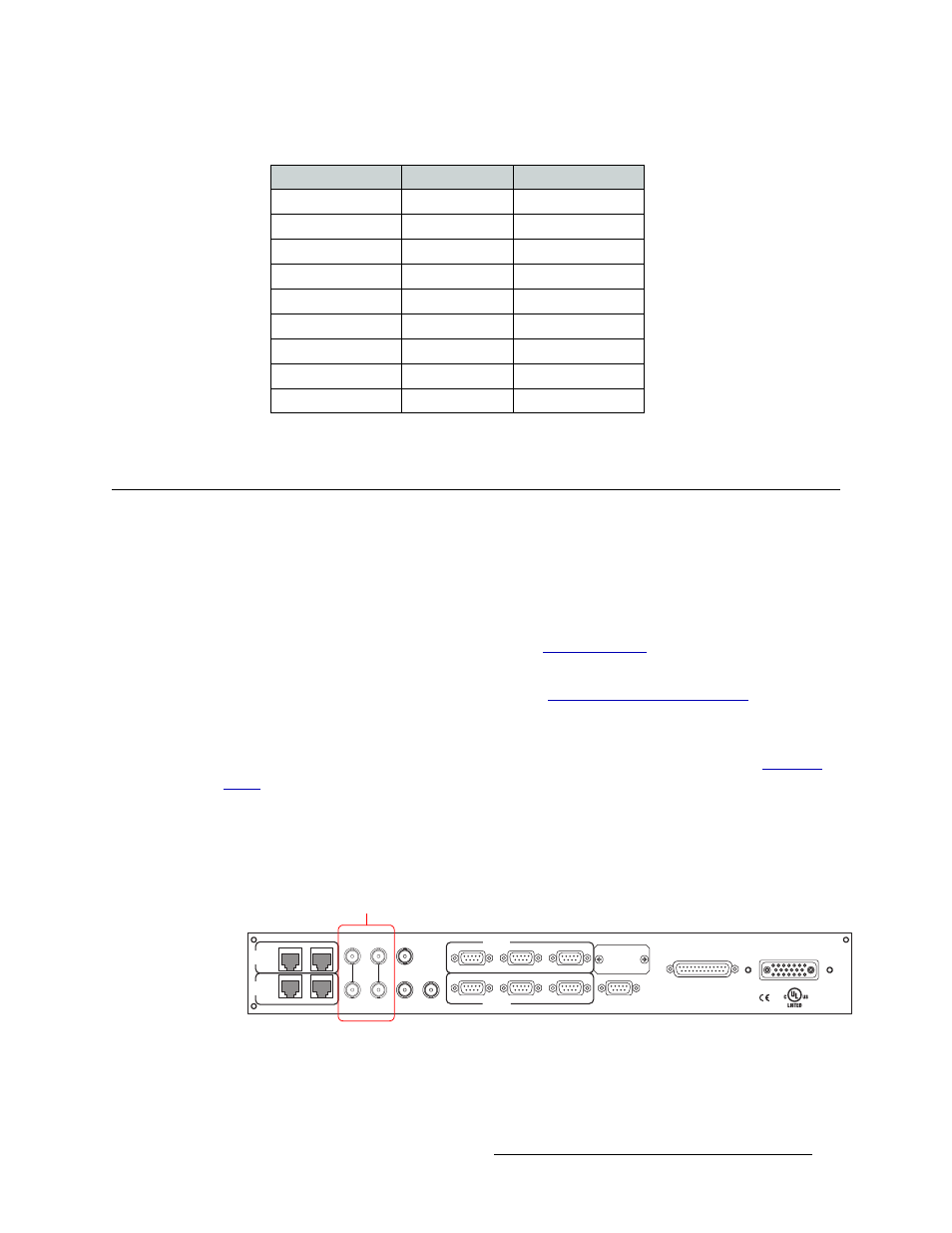
1 Locate the video reference connections on the rear of the router, as shown in Figure 3-18. The
video reference connections are labeled ‘VIDEO REF1’ and ‘VIDEO REF2’.
Figure 3-18. Video Reference Connections and BNC Connector (Rear View)
2 Connect to the ‘VIDEO REF 1’ connection using a 75
ohm BNC connector and coaxial cable.
3 Connect the other end of the cable to a reference signal. Be sure the incoming signal is from a
stable source. The signals can be:
PC End
Pins
Router End
Ground
1 ------------1
Ground
Rx–
2 ------------2
Tx–
Tx+
3 ------------3
Rx+
Tx Common
4 ------------4
Rx Common
N/C
5 ------------5
N/C
Rx Common
6 ------------6
Tx Common
Rx+
7 ------------7
Tx+
Tx–
8 ------------8
Rx–
Ground
9 ------------9
Ground
RTR EXPANSION
E146905
10/100 BT
10/100 BT
RTR EXPANSION
VIDEO
REF 1
LOOP
VIDEO
REF 2
LOOP
AUX 1
AUX 2
CTRL 1
CTRL 1
CTRL 2
CTRL 2
ALARMS
POWER SUPPLY
MONITORS
POWER INPUT
TIME
CODE
PRI
CTRL
SEC
CTRL
PRI CTRL
SEC CTRL
DIAG (38.4 Kbaud)
DIAG (38.4 Kbaud)
Video Reference
Connectors