Introduction – Grass Valley NV8288 v.1.5 User Manual
Page 20
10
Rev 1.5 • 24 Sep 09
2. Introduction
Module Slots and Rear Connectors
If the NV8288-Plus router is used as a standalone router, only the 6 local outgoing signal connec-
tions are used. If the router is connected to another NV8288-Plus router, each expansion connection
send signals to the connected router, as follows: output slot 1 sends outputs 289–294 to the con-
nected router, output slot 2 sends outputs 295–300 to the connected router, and so on, up to 576.
Similarly, the connected router sends outputs to the local router in the same manner, doubling out-
puts. Inputs are also doubled, so that the two routers have a combined total of 576 inputs and 576
outputs.
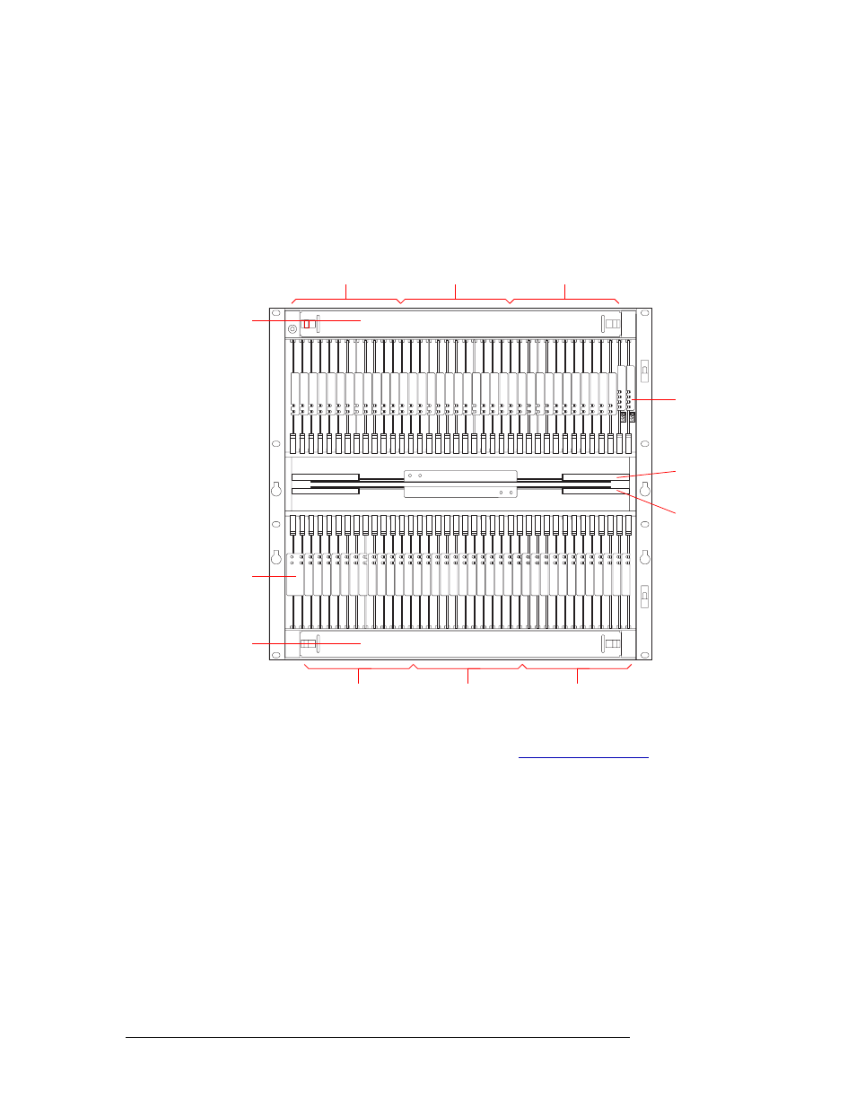
Figure 2-6. NV8288-Plus Router with Door Removed (Front View)
For information on installing cards in modules slots, see
The rear of the NV8288-Plus (Figure 2-7, next page) features non-interchangeable backplanes con-
taining 288 I/O DIN 1.0/2.3 connections for receiving signals and 288 DIN 1.0/2.3 connections for
distributing signals, plus 48 expansion connections for sending signals between two connected
NV8288-Plus routers. By connecting two routers you can receive and distribute up to 576 signals.
Note that the outputs and inputs are numbered from right to left because the router is being viewed
from the rear.
Output Cards(12)
Outputs 1–72
Input Cards (12)
Inputs 1–144
Output Cards (12)
Outputs 73–144
Control Cards (2)
Monitor
Module (1)
Output Cards (12)
Outputs 145–216
Input Cards (12)
Inputs 145–288
Output Cards (12)
Outputs 217–288
Fan Tray
Fan Tray
Crosspoint Cards (2):
Top Card for local
outputs 1–288
Bottom Card for external
outputs 1–288