Installation – Grass Valley NV8288 v.1.5 User Manual
Page 56
46
Rev 1.5 • 24 Sep 09
3. Installation
Making Monitor Connections
router’s connection to the monitoring equipment. For simplicity, this procedure refers to each router
as the primary or secondary router.
How to Make Monitor Expansion Connections
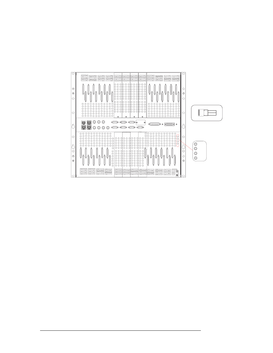
1 Locate the monitor connections on the rear of the router, as shown in Figure 3-20.
Figure 3-20. Monitor Expansion Connections and DIN 1.0/2.3 Connectors (Rear View) on the NV8288-Plus
2 On the secondary router (the router that does not have direct connections to the monitoring
equipment), connect to the ‘OUT 1’ monitor connection using a DIN 1.0/2.3 connector and
Belden 1855A cable, or an equivalent.
3 Connect the other end of the cable to the ‘IN 1’ monitor connection on the primary router (the
router with direct connections to the monitoring equipment), as shown in Figure 3-21.
IN 1
IN 2
OUT 1
OUT 2
Monitor connections
Mini-DIN 1.0/2.3 Connector