Making alarm connections, Installation – Grass Valley NV8288 v.1.5 User Manual
Page 57
NV8288 and NV8288-Plus Digital Video Routers • User’s Guide
47
3. Installation
Making Alarm Connections
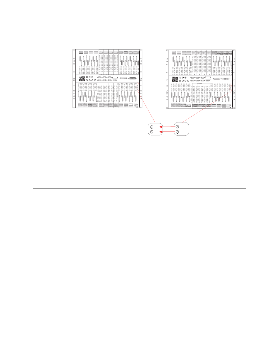
Figure 3-21. Monitor Connections Between Two NV8288-Plus Routers (Rear View)
4 On the secondary router, connect to the ‘OUT 2’ monitor connection using a DIN 1.0/2.3 con-
nector and Belden 1855A cable, or an equivalent.
5 Connect the other end of the cable to the ‘IN 2’ monitor connection on the primary router, as
shown in Figure 3-21.
Making Alarm Connections
The router provides system alarms that notify you of a malfunction, such as when a fan or power
supply is not functioning properly. Alarms can be connected to an external alarm indicator that dis-
play visual signals when an alarm is activated. The NV6257 power supply, the NV8000 power sup-
ply, and the router each have alarm connections. Miranda does not provide external indicator
equipment, however this manual provides instruction on wiring the alarm connection. See
Both the NV6257, NV8000, and the router send status information to the router control system. For
more information on the alarm connections, see
How to Make Alarm Connections
1 On the rear of the NV6257 (Figure 3-1) or the NV8000 (Figure 3-5), locate the ‘Alarms’ con-
nection.
2 Connect to the ‘Alarms’ connection using a DB25 connector and cable.
3 Connect the other end of the cable to an external alarm indicator. See
on page 48 for information on wiring the DB25 connector.
Primary Router
Secondary Router
OUT 1
OUT 2
IN 1
IN 2
Connect the OUT
monitor connections
on the secondary router
to the IN
monitor connections
on the primary
router.