Rigid tapping, 3 rigid tapping – HEIDENHAIN TNC 335 Technical Manual User Manual
Page 200
8/95
TNC 360
4 Spindle
4-103
4.4.3 Rigid tapping
Tapping without a floating tap holder is defined in the NC program by "CYCL DEF 17 RIGID
TAPPING" and called by CYCL CALL . Here too the dynamic behavior is determined by machine
parameters.
Before tapping, the axes (e.g. Z and S) are synchronized by a spindle orientation, i.e. each Z position
is assigned to a particular spindle position. This means, that the same thread can be cut more than
once. The fixed assignment of the spindle position depends on the thread pitch which is entered in
the cycle. Because of the fixed thread pitch the correlated Z-dependent spindle position can not be
altered by the operator. The thread pitch can be positive or negative.
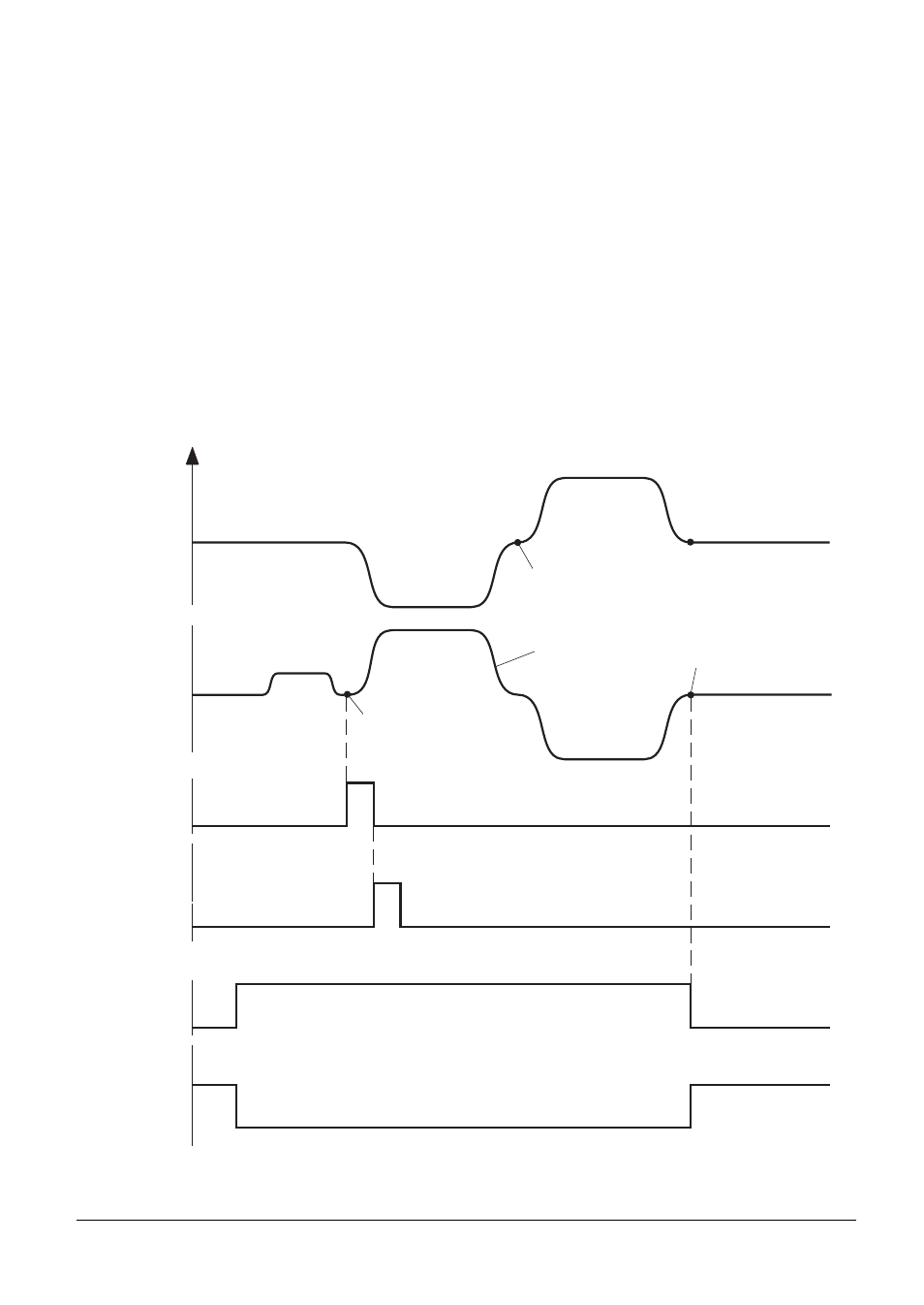
Marker M2095 is set at the start of the cycle. With this marker the PLC program can switch on the
spindle, if required, with M03 or M04. The marker M2499 (Close control loop - S-axis) must be set to
zero in acknowledgment. Only then can the orientation take place, and spindle and tool axis move
synchronously until the cycle has been completely processed. Before orientation the NC outputs an
M05. An acknowledgment is necessary.
After this, marker M2095 is reset by the NC and the control loop is opened. The spindle position is
displayed during tapping. The ramps for the drilling process are stored in MP3410.3.
0
F
0
S
M05
Rückmeldung
M-Funktion
Positionierfenster
erreicht (MP7150)
Rampe aus
MP3410.3
orientierter Halt
orientierter Halt
M2095
M2499
Zyklus
Start
Zyklus
Ende
End of cycle
Cycle start
Acknowledge-
ment of
M function
Oriented stop
Oriented stop
Ramp from
MP3410.3
Positioning window
reached (MP7150)