HEIDENHAIN TNC 620 (81760x-02) ISO programming User Manual
Page 400
Programming: Multiple axis machining
12.2 The PLANE function: Tilting the working plane (software option 8)
12
400
TNC 620 | User's ManualDIN/ISO Programming | 2/2015
Abbreviations used
Abbreviation
Meaning
EULER
Swiss mathematician who defined these
angles
EULPR
Pr
ecession angle: angle describing the rotation
of the coordinate system around the Z axis
EULNU
Nu
tation angle: angle describing the rotation
of the coordinate system around the X axis
shifted by the precession angle
EULROT
Rot
ation angle: angle describing the rotation of
the tilted machining plane around the tilted Z
axis
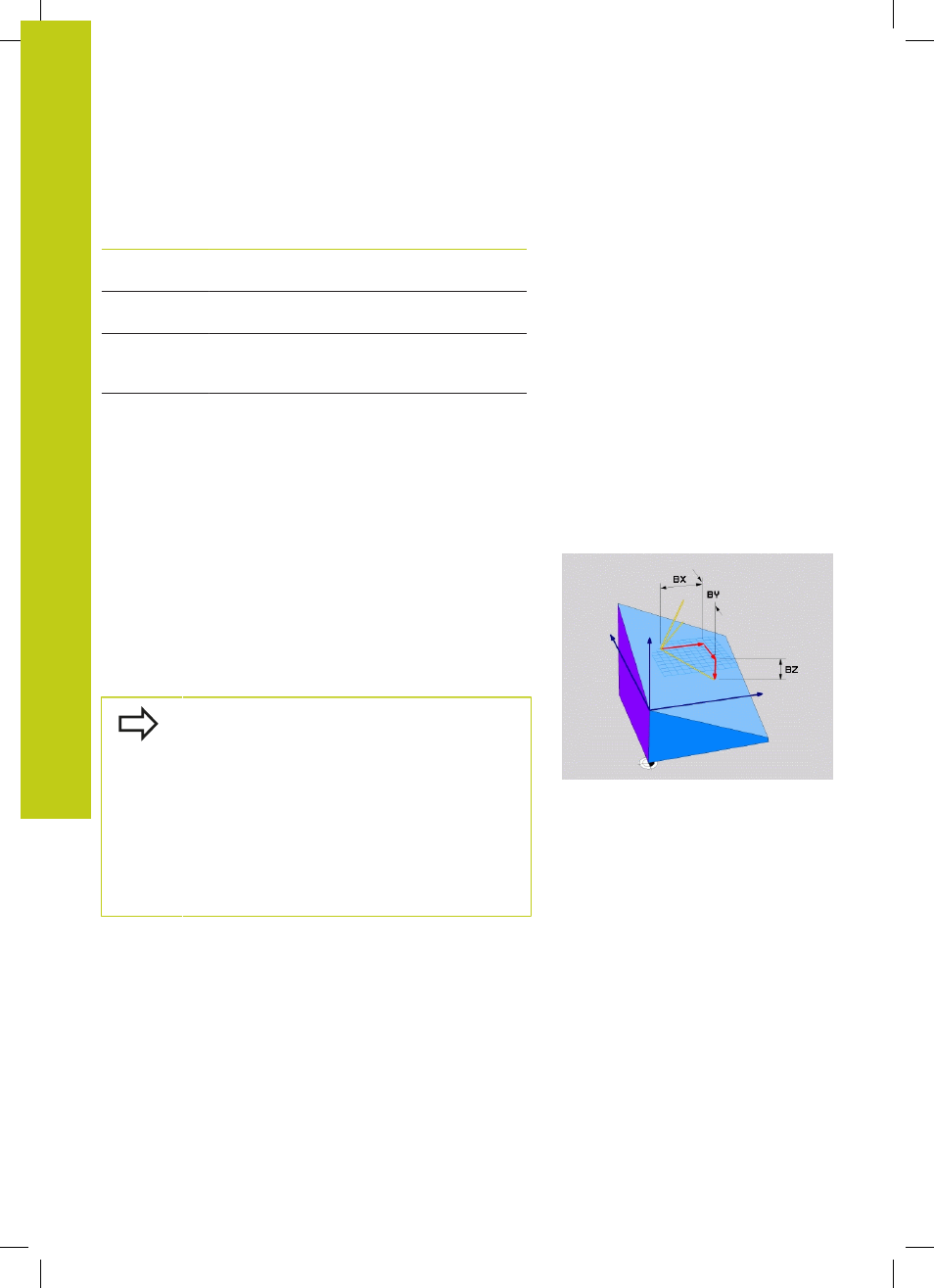
Defining the working plane with two vectors:
PLANE VECTOR
Application
You can use the definition of a working plane via
two vectors
if
your CAD system can calculate the base vector and normal vector
of the tilted machining plane. A normalized input is not necessary.
The TNC calculates the normal, so you can enter values between
–9.999999 and +9.999999.
The base vector required for the definition of the machining plane is
defined by the components
BX, BY and BZ (see figure at right). The
normal vector is defined by the components
NX, NY and NZ.
Before programming, note the following
The base vector defines the direction of the
principal axis in the tilted machining plane, and the
normal vector determines the orientation of the
tilted machining plane, and at the same time is
perpendicular to it.
The TNC calculates standardized vectors from the
values you enter.
Parameter description for the positioning behavior: