31 gear hobbing (cycle 880, din/iso: g880), Cycle run, Gear hobbing (cycle 880, din/iso: g880) – HEIDENHAIN TNC 640 (34059x-05) Cycle programming User Manual
Page 425
GEAR HOBBING (Cycle 880, DIN/ISO: G880) 12.31
12
TNC 640 | User's Manual Cycle Programming | 1/2015
425
12.31
GEAR HOBBING (Cycle 880, DIN/ISO:
G880)
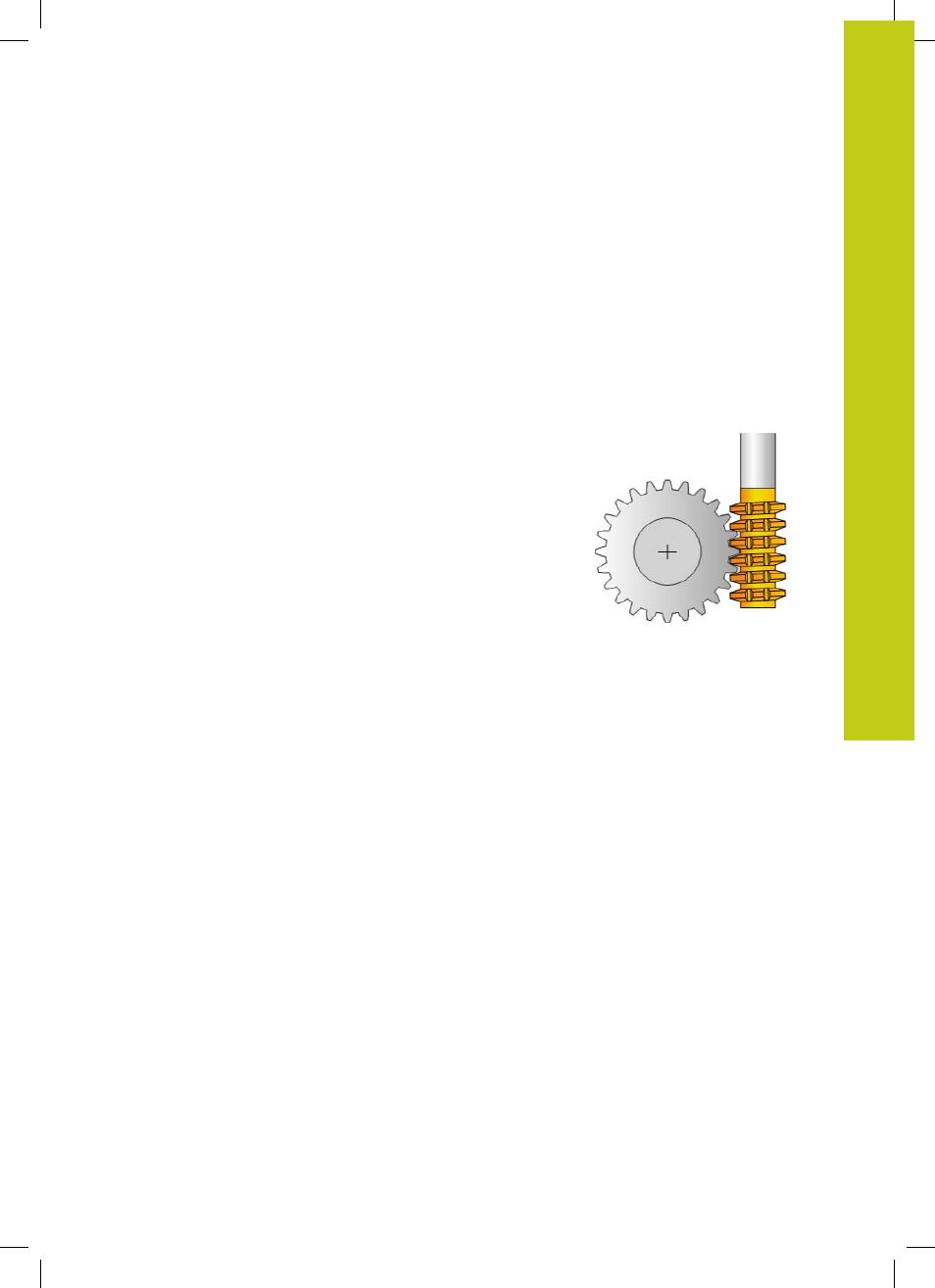
Cycle run
With Cycle 880 Gear Hobbing you can machine external cylindrical
gears or helical gears with any angles. In the cycle you first define
the
gear
and then the
tool
with which the gear is to be machined.
You can select the machining strategy and the machining side in
the cycle. The machining process for gear hobbing is performed
with a synchronized rotary motion of the tool spindle and rotary
table. In addition, the gear hob moves along the workpiece in axial
direction.
While Cycle 880 Gear Hobbing is active, the coordinate system
might be rotated. It is therefore essential to program Cycle
801
RESET ROTARY COORDINATE SYSTEM
and
M145
at the end of
the cycle.
Cycle run:
1 The TNC positions the tool in the tool axis to clearance height
Q260 at the feed rate FMAX. If the value of the current tool
location in the tool axis is greater than Q260, the tool is not
moved.
2 Before tilting the working plane, the TNC positions the tool in X
to a safe coordinate at the feed rate FMAX. If the tool is already
located at a coordinate in the working plane that is greater than
the calculated coordinate, the tool is not moved.
3 The TNC then tilts the working plane at the feed rate Q253;
M144
is internally active in the cycle.
4 The TNC positions the tool at the feed rate FMAX to the starting
point in the working plane.
5 The TNC then moves the tool in the tool axis at the feed rate
Q253 to the set-up clearance Q460.
6 The TNC moves the hob in the longitudinal direction at the
programmed feed rate Q478 (for roughing) or Q505 (for
finishing) along the workpiece into which the teeth are to be
cut. The area to be machined is limited by the starting point in Z
Q551+Q460 and the end point in Z Q552+Q460.
7 When the tool reaches the end point, it is retracted at the feed
rate Q253 and returns to the starting point.
8 The TNC repeats the steps 5 to 7 until the defined gear is
completed.
9 Finally, the TNC retracts the tool to the clearance height Q260 at
the feed rate FMAX.
10 The machining operation ends in the tilted system.
11 Now you need to move the tool to a safe height and reset the
tilting of the working plane.
12 Then you must program Cycle 801 RESET ROTARY
COORDINATE SYSTEM and
M145
.