97 adapter 15/15-pin htl/htls – HEIDENHAIN PWM 20 User Manual
Page 160
August 2014
Pin layouts
161
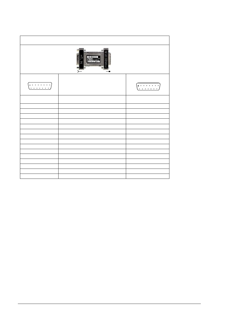
4.3.97 Adapter 15/15-pin HTL/HTLs
* Switchover I
2
C-PWM20_AdapterHTL on/off via: PWM20.ioPorts.EN_SHIELD
The assignment of the female connector is set via the active PWM 20 input (X1) according to
the connected encoder.
1
9
2
10
3
5
4
6
8
7
11 12 13 14 15
8
15
7
14
6
4
5
3
1
2
13 12 11 10 9
Messgerät
Encoder
PWM 20
Adapter ID 1093210-01
Adapter ID 1093210-01
Signal (vom Messgerät vorgegeben)
Signal (prescribed by the encoder)
Stecker 15-pol. Buchse
15-pin connector (female)
Stecker 15-pol. Stift
15-pin connector (male)
PIN 1
HTL: +Ua1
PIN 1
PIN 2
0 V
PIN 2
PIN 3
HTL: +Ua2
PIN 3
PIN 4
HTL: U
P
PIN 4
PIN 5
EnDat: +DATA
PIN 5
PIN 6
Schirm * / shield
PIN 6
PIN 7
HTL: -Ua0
PIN 7
PIN 8
EnDat: +CLOCK
PIN 8
PIN 9
HTL: -Ua1
PIN 9
PIN 10
HTL: -Sensor
PIN 10
PIN 11
HTL: -Ua2
PIN 11
PIN 12
HTL: +Sensor
PIN 12
PIN 13
HTL: +UaS; EnDat: -DATA; I
2
C: DAT
PIN 13
PIN 14
HTL: +Ua0
PIN 14
PIN 15
EnDat: -CLOCK; I
2
C: DAT
PIN 15