3 overview of cables and adapters, 3overview of cables and adapters – HEIDENHAIN PWM 20 User Manual
Page 18
August 2014
Overview of cables and adapters
19
3
Overview of cables and adapters
3.1
General information: PWM 20 - encoder connection and grounding
Encoder
connection
Please ensure that the correct supply voltage is selected to avoid damage to the encoder.
The cable between the encoder and the PWM 20 must not be connected or disconnected while
under power. Otherwise the encoder and the PWM 20 might be damaged. Check whether the
cable between the encoder and the PWM 20 is correctly wired. The pin layout of the encoder is
included in the specifications. The pin layouts of the connecting cables are described in the
catalog. An incorrectly wired connecting cable might damage the encoder and the PWM 20.
Encoder
output
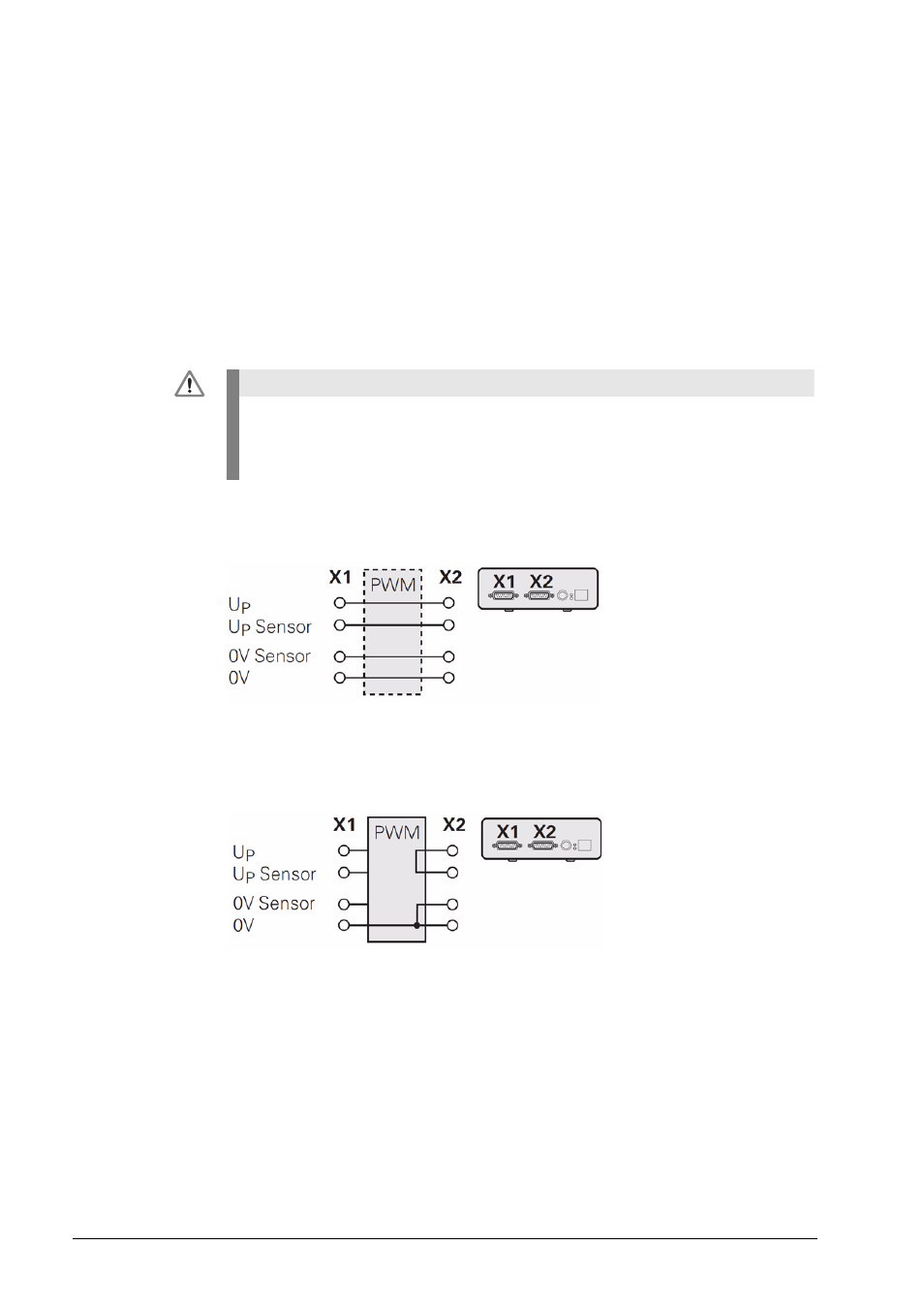
The encoder input X1 of the PWM 20 is electrically connected with the encoder output X2.
The signals and the pin layout at the output correspond to the respective signals at the input.
Example 1:
PWM 20 in feed-through mode (the encoder is powered by the subsequent electronics) / ATS
software not started
Example 2:
PWM 20 powers the encoder via X1
DANGER
There is no metallic isolation of the signals.
The supply and sensor lines are switched via the ATS software (as of ATS V2.6) depending
on the respective mode of operation, and can be connected (see examples).
It is always ensured that the supply voltage generated by the PWM 20 is not present at X2.