54
HEIDENHAIN PWM 20 Testing Package – Cable and Connection Technology
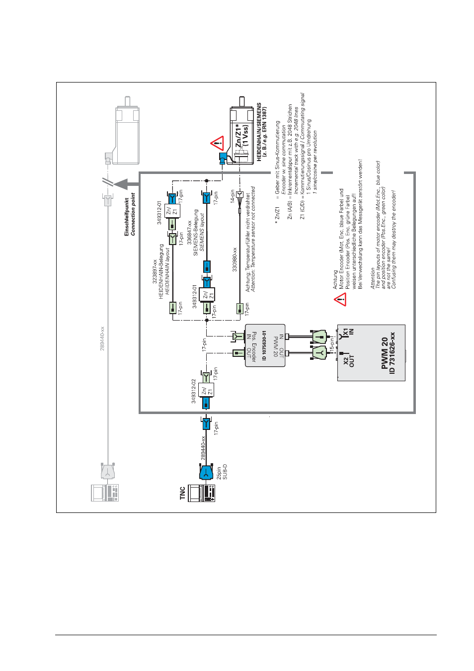
Figure B
Measured at the servo motor (17-pin flange socket) or a at the PCB connector of the motor encoder (motor side):
Synchronous motors
Commutation signals
1 Vpp Zn/
Z1
A
BCD