2 pin layout of ik 215 – HEIDENHAIN PWM 20 User Manual
Page 63
64
HEIDENHAIN PWM 20 Testing Package – Cable and Connection Technology
4.2
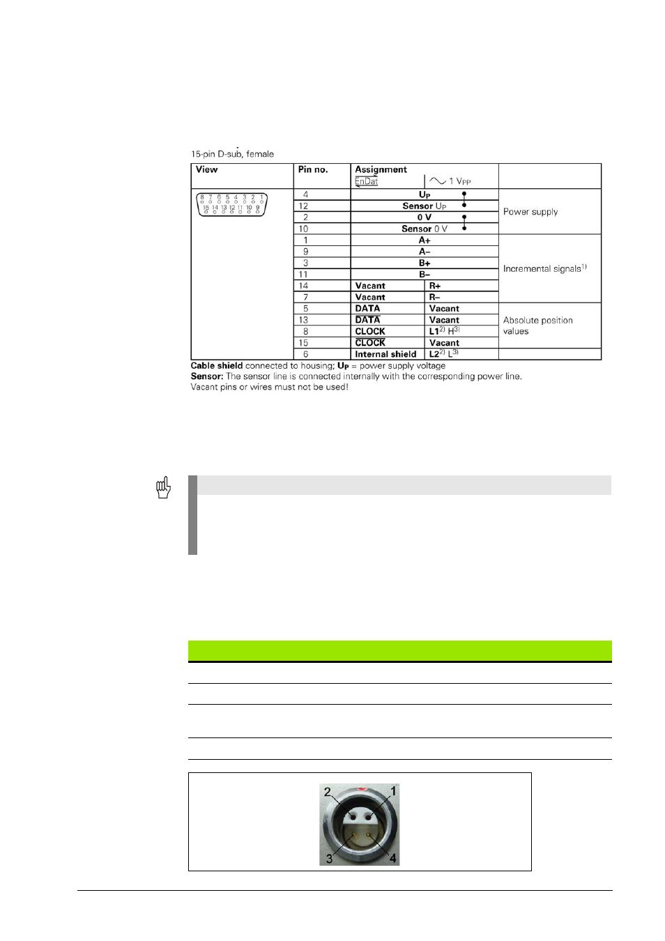
Pin layout of IK 215
Connection of encoder X1
The encoder is connected to the encoder input X1. The layout of the 15-pin D-sub connector is
as follows:
1)
Only with ordering designations EnDat 01 and EnDat 02
2)
Only for LIDA 4xx with limit signal
3)
Only for LIF 481 with limit and homing signal
Shield on housing; Up = power supply
Unused pins must not be assigned!
Connection for the external functions X3
For external functions, a 4-pin female connection is available through which the recording of
measured values can be externally controlled. The required connector can be ordered from
HEIDENHAIN under the ID 282 168-01. The signals are arranged as follows (view of the socket
from outside):
Attention
The power supply of the encoder (pin 4) can be selected by software. Care must be taken
that the correct supply voltage is set at the encoder, since otherwise the encoder, the IK or
the computer may be damaged! Connect or disconnect the encoders only while the power
supply is switched off!
Pin
Assignment
1
Input: Latch pulse (HEIDENHAIN internal use)
2
Output: Synchronization pulse (HEIDENHAIN internal use)
3
Output: MSB of position value (singleturn), serves as mounting aid for EnDat
motor encoders.
4
GND