2 encoder connector (cn2) terminal layout, 9 (2) absolute encoders – Yaskawa Sigma II Series SGMVH User Manual
Page 134
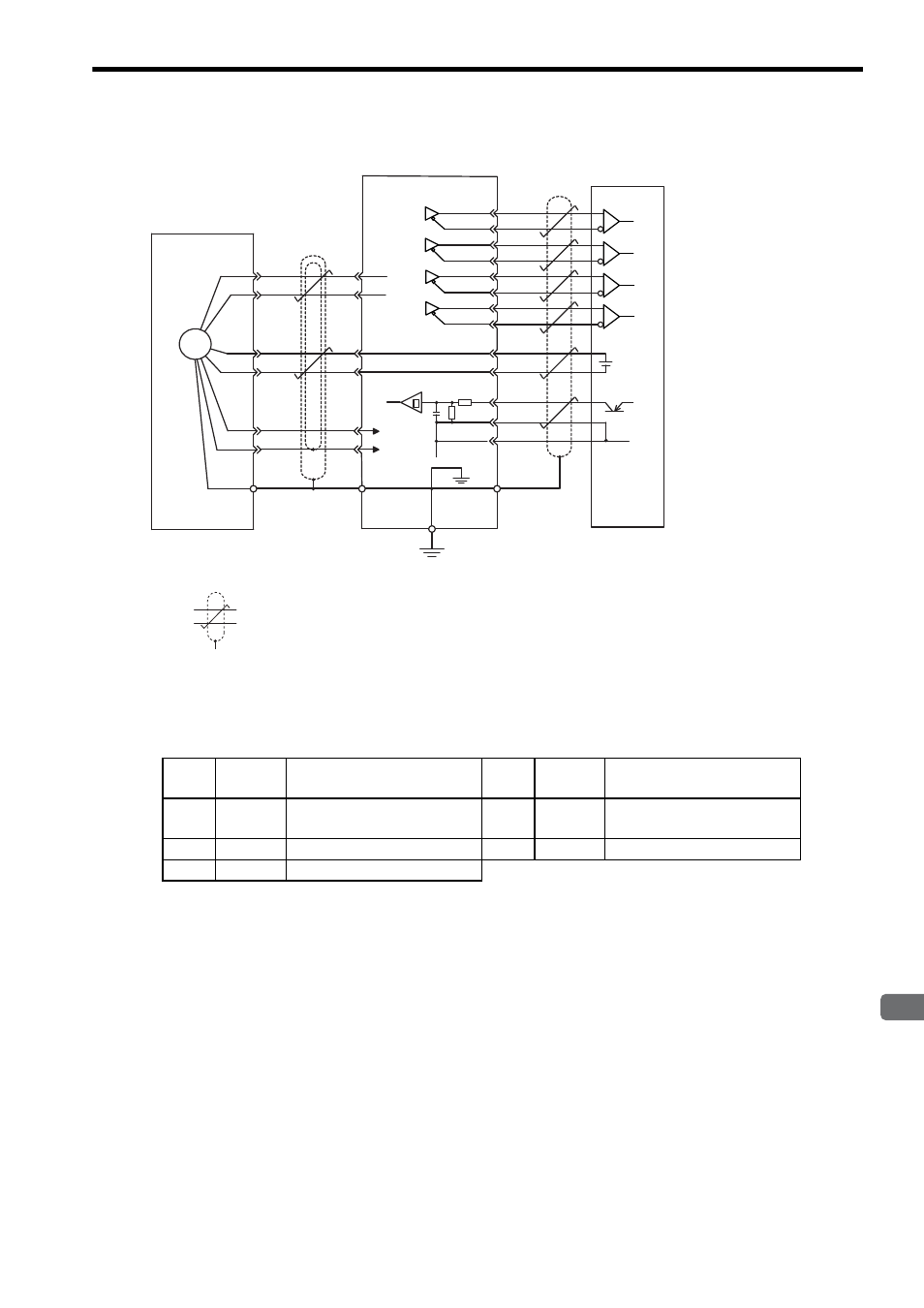
6.2 Wiring Encoders
6
Wiring
6-9
(2) Absolute Encoders
* 1.
: represents twisted-pair wires.
* 2. Applicable line receiver: SN75175 manufactured by Texas Instruments or the equivalent.
6.2.2 Encoder Connector (CN2) Terminal Layout
+
–
C
D
T
S
H
G
J
PG5 V
PG0 V
0 V
CN2
2-5
2-6
2-3
2-4
2-1
2-2
CN1
+5 V
0 V
1-33
PAO
1-34
/PAO
1-35
PBO
1-36
/PBO
1-19
PCO
1-20
/PCO
1-48
PSO
1-49
/PSO
1-21
BAT(+)
1-22
BAT(–)
1-4
SEN
1-2
SG
1-1 SG
∗1
∗2
PG
Absolute encoder
SERVOPACK
Orange
White/orange
Connector
shell
Connector
shell
Battery
Red
Inner
shield
Outer
shield
Blue
White/blue
Customer end
1
PG5V
PG power supply
+5 V
2
PG 0 V
PG power supply
0 V
3
BAT (+)
Battery (+)
(For an absolute encoder)
4
BAT (-)
Battery (-)
(For an absolute encoder)
5
PS
PG serial signal input
6
/PS
PG serial signal input
SHELL Shield
−