JBL Synthesis SDA 4600 User Manual
Page 11
11 |
J B L S y n t h e s i s S D A 8 3 0 0 / S D A 4 6 0 0 S y s t e m G u i d e
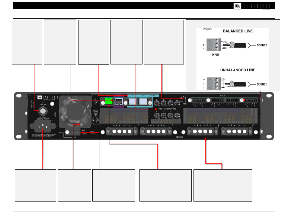
Rear panel description
Power Fuse
F20AH 250V,
replace with same
type fuse.
LittelFuse 314
Series.
AC Power Inlet
Standard IEC type 320 inlet
for detachable connector
100 - 240 V~.
Cooling Fan
Outlet
Outlets for cooling air
flow. Do not block or
cover these outlets.
Auxiliary Connector
3-pin plug-in type connector,
Enables SLEEP mode and
monitoring of AMP STATUS
unless the amplifier is in any
of these conditions: OFF,
SLEEP, or FAULT.
Output Connectors
One four-pole touch-proof terminal strip
per channel pair. Accepts up to 10 AWG
wire or terminal forks.
Ethernet
For monitoring and
control of the
amplifier over
Category 5e wiring.
For advanced setup
and Factory Service
Only. Do not use
this unless directed
by technical
support.
BLU Link
Input/Output
Ring
Up to 256
channels of digital
audio over
Category 5e
wiring. Only 60
nodes should be
used in the BLU-
Link Ring.
Input
Attenuators
One 21-position
detented
potentiometer per
channel.
Logarithmic audio
taper. Attenuation
range mute to 0 dB.
Backup Analog Input Connectors
One 6-pin plug-in
connector per input pair. High impedance balanced
GPIO
Use this input with the supplied
configuration plugs to change the
routing of the internal digital audio
and amplifier setup.
Preset Indicators
Visual LED light indicator
of the currently selected
preset. The LED will blink
rapidly and then pause to
indicate what number
Preset is selected. NOTE:
The factory Preset is #2.
Configuration 2 is Preset
3 and Configuration 3 is
Preset 4.