Typical applications – Linx Technologies TRM-xxx-NT User Manual
Page 14
– –
– –
22
23
Figure 28 shows the 900MHz channels avaiable through the module's
serial Command Data Interface.
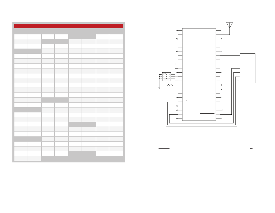
Typical Applications
Figure 29 shows a circuit using the NT Series transceiver.
The channel select lines are controlled with a DIP switch, so changing the
switches changes the channel. DATA_IN and DATA_OUT are connected to
GPIOs on a microcontroller that generates and decodes the over-the-air
data. READY and RSSI are monitored by the microcontroller and T/R_SEL,
POWER_DOWN and STANDBY are controlled by the microcontroller.
The BAUD lines are tied low, placing the module into a single baud band
(19.2kbps). This circuit allows the microcontroller to monitor and control the
power state of the module while the end user manually selects the channel.
GND
GND
GND
GND
GND
GND
VCC
NC
2
GND
3
NC
4
NC
5
GND
6
NC
7
TRPT/PKT
9
CHN_SEL
0
10
GND
11
T/R_SEL
18
BAUD0
19
RSSI
21
GND
22
GND
23
POWER_DOWN
24
VCC
25
STANDBY
26
CMD_DATA
_IN
27
CHN_SEL
1
12
GND
17
CHN_SEL
2
13
LVL_ADJ
14
READY
15
NC
16
NC
8
BAUD1
20
GND
1
GND
28
CMD_DATA
_OUT
29
CMD_DATA
_TYPE
30
CMD_DATA
_BAUD
31
NC
32
NC
33
GND
34
NC
35
NC
36
DATA_OUT
37
DATA_IN
38
GND
39
NC
40
NC
41
GND
42
ANTENNA
43
GND
44
GND
GND
GND
GND
GND
VCC
GND
GND
GND
VCC
GND
GND
GPIO
GPIO
GPIO
GPIO
GPIO
GPIO
GPIO
µ
GND
GND
GND
GND
GND
GND
VCC
NC
2
GND
3
NC
4
NC
5
GND
6
NC
7
TRPT/PKT
9
CHN_SEL
0
10
GND
11
T/R_SEL
18
BAUD0
19
RSSI
21
GND
22
GND
23
POWER_DOWN
24
VCC
25
STANDBY
26
CMD_DATA
_IN
27
CHN_SEL
1
12
GND
17
CHN_SEL
2
13
LVL_ADJ
14
READY
15
NC
16
NC
8
BAUD1
20
GND
1
GND
28
CMD_DATA
_OUT
29
CMD_DATA
_TYPE
30
CMD_DATA
_BAUD
31
NC
32
NC
33
GND
34
NC
35
NC
36
DATA_OUT
37
DATA_IN
38
GND
39
NC
40
NC
41
GND
42
ANTENNA
43
GND
44
GND
GND
GND
GND
GND
GND
GND
GND
TX
GPIO
GPIO
GPIO
RX
µ
GND
GPIO
Figure 29: NT Series Transceiver Typical Application
NT Series Transceiver 900MHz Serial Channels
Channel Frequecy Channel Frequecy Channel Frequecy Channel Frequecy
0
902.62
26
909.12
51
915.37
76
921.62
1
902.87
27
909.37
52
915.62
77
921.87
2
903.12
28
909.62
53
915.87
78
922.12
3
903.37
29
909.87
54
916.12
79
922.37
4
903.62
30
910.12
55
916.37
80
922.62
5
903.87
31
910.37
56
916.62
81
922.87
6
904.12
32
910.62
57
916.87
82
923.12
7
904.37
33
910.87
58
917.12
83
923.37
8
904.62
34
911.12
59
917.37
84
923.62
9
904.87
35
911.37
60
917.62
85
923.87
10
905.12
36
911.62
61
917.87
86
924.12
11
905.37
37
911.87
62
918.12
87
924.37
12
905.62
38
912.12
63
918.37
88
924.62
13
905.87
39
912.37
64
918.62
89
924.87
14
906.12
40
912.62
65
918.87
90
925.12
15
906.37
41
912.87
66
919.12
91
925.37
16
906.62
42
913.12
67
919.37
92
925.62
17
906.87
43
913.37
68
919.62
93
925.87
18
907.12
44
913.62
69
919.87
94
926.12
19
907.37
45
913.87
70
920.12
95
926.37
20
907.62
46
914.12
71
920.37
96
926.62
21
907.87
47
914.37
72
920.62
97
926.87
22
908.12
48
914.62
73
920.87
98
927.12
23
908.37
49
914.87
74
921.12
99
927.37
24
908.62
50
915.12
75
921.37
100
927.62
25
908.87
Dark Gray = Hardware Selectable Channels
Figure 28: NT Series Transceiver 900MHz Serial Channels