General antenna rules – Linx Technologies TRM-xxx-NT User Manual
Page 19
– –
– –
32
33
General Antenna Rules
The following general rules should help in maximizing antenna performance.
1. Proximity to objects such as a user’s hand, body or metal objects will
cause an antenna to detune. For this reason, the antenna shaft and tip
should be positioned as far away from such objects as possible.
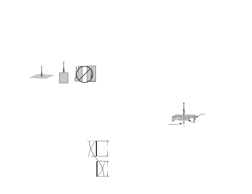
2. Optimum performance is obtained from a ¼- or ½-wave straight whip
mounted at a right angle to the ground plane (Figure 38). In many
cases, this isn’t desirable for practical or ergonomic reasons, thus,
an alternative antenna style such as a helical, loop or patch may be
utilized and the corresponding sacrifice in performance accepted.
3. If an internal antenna is to be used, keep it away from other metal
components, particularly large items like transformers, batteries,
PCB tracks and ground planes. In many cases, the space around the
antenna is as important as the antenna itself. Objects in close proximity
to the antenna can cause direct detuning, while those farther away will
alter the antenna’s symmetry.
4. In many antenna designs, particularly ¼-wave whips, the ground plane
acts as a counterpoise, forming, in essence,
a ½-wave dipole (Figure 39). For this reason,
adequate ground plane area is essential.
The ground plane can be a metal case or
ground-fill areas on a circuit board. Ideally, it
should have a surface area less than or equal
to the overall length of the ¼-wave radiating
element. This is often not practical due to
size and configuration constraints. In these
instances, a designer must make the best use
of the area available to create as much ground
OPTIMUM
USABLE
NOT RECOMMENDED
NUT
GROUND PLANE
(MAY BE NEEDED)
CASE
Figure 38: Ground Plane Orientation
plane as possible in proximity to the base of the antenna. In cases
where the antenna is remotely located or the antenna is not in close
proximity to a circuit board, ground plane or grounded metal case, a
metal plate may be used to maximize the antenna’s performance.
5. Remove the antenna as far as possible from potential interference
sources. Any frequency of sufficient amplitude to enter the receiver’s
front end will reduce system range and can even prevent reception
entirely. Switching power supplies, oscillators or even relays can also
be significant sources of potential interference. The single best weapon
against such problems is attention to placement and layout. Filter the
module’s power supply with a high-frequency bypass capacitor. Place
adequate ground plane under potential sources of noise to shunt noise
to ground and prevent it from coupling to the RF stage. Shield noisy
board areas whenever practical.
6. In some applications, it is advantageous to place the module and
antenna away from the main equipment (Figure 40). This can avoid
interference problems and allows the antenna to be oriented for
optimum performance. Always use 50
Ω coax, like RG-174, for the
remote feed.
I
E
DIPOLE
ELEMENT
GROUND
PLANE
VIRTUAL
λ/4
DIPOLE
λ/4
λ/4
VERTICAL
λ/4 GROUNDED
ANTENNA (MARCONI)
Figure 39: Dipole Antenna
OPTIMUM
USABLE
NOT RECOMMENDED
NUT
GROUND PLANE
(MAY BE NEEDED)
CASE
Figure 40: Remote Ground Plane