Pin assignments, Pin descriptions, Pin assignments pin descriptions – Linx Technologies TRM-xxx-NT User Manual
Page 9
– –
– –
12
13
GND
NC
GND
GND
NC
NC
GND
DATA_IN
DATA_OUT
NC
NC
NC
GND
NC
GND
ANTENNA
1
2
3
4
5
6
7
8
37
38
39
40
41
42
43
44
TRPT/PKT
CHN_SEL0
GND
GND
NC
NC
CMD_DATA_BAUD
CMD_DATA_TYPE
CMD_DATA_OUT
READY
CHN_SEL1
CHN_SEL2
LVL_ADJ
NC
NC
NC
9
10
11
12
13
14
15
16
29
30
31
32
33
34
35
36
GND
T/R_SEL
BAUD0
STANDBY
VCC
POWER_DOWN
GND
BAUD1
RSSI
GND
GND
CMD_DATA_IN
17
18
19
20
21
22
23
24
25
26
27
28
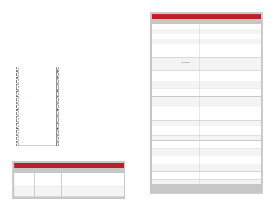
Pin Descriptions
Pin Number
Name
Description
1, 3, 6, 11,
17, 22, 23,
28, 34, 39,
42, 44
GND
Ground
2, 4, 5, 7, 8,
16, 32, 33,
35, 36, 40, 41
NC
No Connection
Pin Assignments
Pin Descriptions
A low-power onboard communications processor performs the radio
control and management functions. An interface processor performs the
higher level functions and controls the serial and hardware interfaces.
This block also includes voltage translation to allow the internal circuits to
operate at a low voltage to conserve power while enabling the interface to
operate over the full external voltage. This prevents hardware damage and
communication errors due to voltage level differences.
While operation is recommended from 3.3V to 5.0V, the transceiver can
operate down to 2.5V.
Figure 21: NT Series Transceiver Pinout (Top View)
Pin Descriptions Continued
Pin Number
Name
Description
9
TRPT / PKT
1,2
Transparent/Packet Data Select. Pull high or float.
10
CHN_SEL0
1
Parallel Channel Select 0
12
CHN_SEL1
1
Parallel Channel Select 1
13
CHN_SEL2
1
Parallel Channel Select 2
14
LVL_ADJ
1
Level Adjust. This line sets the transmitter output
power level. Pull high or leave open for the high-
est power; connect to GND through a resistor to
lower the power.
15
READY
Ready. This line is low when the transceiver is
ready to communicate and high when it is busy.
This line can be used for hardware handshaking
on the command port.
18
T/R_SEL
1
Transmit/Receive Select. Pull this line low to place
the transceiver into receive mode. Pull it high to
place it into transmit mode.
19
BAUD0
1
Baud Rate Select 0. This line and BAUD1 set the
over-the-air data rate and filter bandwidths.
20
BAUD1
1
Baud Rate Select 1. This line and BAUD0 set the
over-the-air data rate and filter bandwidths.
21
RSSI
Received Signal Strength Indicator. This line
outputs an analog voltage that is proportional to
the strength of the received signal.
24
POWER_DOWN
Power Down. Pulling this line low places the
module into a low-power state. The module will
not be functional in this state. Pull high for normal
operation.
25
VCC
Supply Voltage
26
STANDBY
1
Standby. Pull this line high or leave floating to put
the module into low-power standby mode. Pull to
GND for normal operation.
27
CMD_DATA_IN
2
Command Data In. Pull high for normal operation.
29
CMD_DATA_OUT
2
Command Data Out. Do not connect for normal
operation.
30
CMD_DATA_TYPE
2
Command Data Type. Pull low for normal
operation.
31
CMD_DATA_BAUD
2
Command Data Baud. Pull low for normal
operation.
37
DATA_OUT
Received Data Output. This line outputs the
demodulated digital data.
38
DATA_IN
Transmit Data Input. This line accepts the data to
be transmitted.
43
ANTENNA
50-ohm RF Antenna Port
1. These lines have an internal 100k
Ω pull-up resistor
2. Contact Linx for more information
Figure 22: NT Series Transceiver Pin Descriptions