Linx Technologies TRM-xxx-NT User Manual
Page 5
– –
– –
4
5
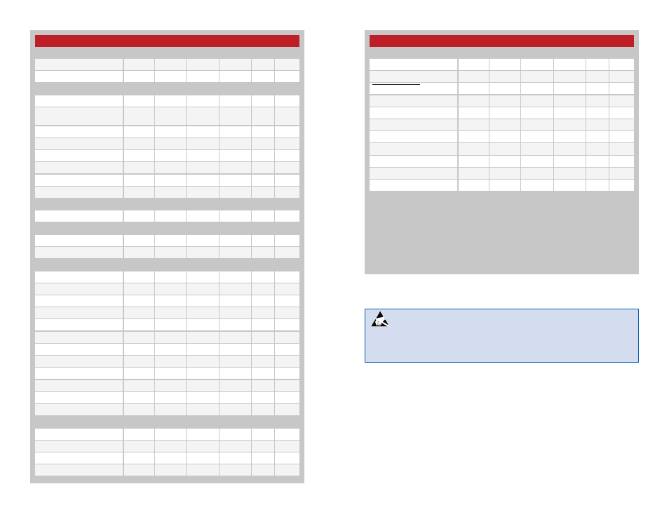
NT Series Transceiver Specifications
Parameter
Symbol
Min.
Typ.
Max.
Units Notes
Logic Low
V
OL
0.3
0.4
VDC
Logic High
V
OH
V
CC
–0.4
0.5*V
CC
VDC
POWER_DOWN
Logic Low
V
I
0.8
VDC
Logic High
V
IH
2
5.5
VDC
Input
Logic Low
V
IL
0.8
VDC
Logic High
V
IH
2
5.5
VDC
Output
Logic Low
V
OL
0.6
VDC
Logic High
V
OH
V
CC
–0.7
V
CC
VDC
1. Measured at 3.3V V
CC
2. Measured at 25ºC
3. Guaranteed by design
4. Characterized but not tested
5. At the band’s low data rate; BER=10
–3
6. Into a 50-ohm load
7. P
O
=+12.5dBm (max output power)
8. Module is not busy performing other
tasks
9. Time starts when supply voltage
reaches V
CC
minimum
10. 68 / 101 channels through the serial
interface
11. Baud Band is a user selected setting
that determines filter settings, max data
rate, receiver sensitivity and transmitter
frequency deviation. See Baud Band
Selection for more details.
NT Series Transceiver Specifications
Parameter
Symbol
Min.
Typ.
Max.
Units Notes
RSSI
Dynamic Range
60
dB
Transmitter Section
Output Power
P
O
−15.5
+12.5
dBm
6
Output Power Control
Range
28
dB
Harmonic Emissions
P
H
−42
–36
dBc
7
Frequency Deviation
Baud Band = 1
±30
kHz
3,11
Baud Band = 2
±55
kHz
3,11
Baud Band = 3
±80
kHz
3,11
Baud Band = 4
±120
kHz
3,11
Antenna Port
RF In/Out Impedance
R
IN
50
Ω
Environmental
Operating Temp. Range
−40
+85
ºC
Storage Temp. Range
−55
+125
ºC
Timing
Receiver Turn-On Time
Via V
CC
5.0
6
ms
4,9
Via Power Down
5.0
6
ms
4,9
Via Standby
0.6
1
ms
4,8
Transmitter Turn-On Time
Via V
CC
5.0
6
ms
4,9
Via Power Down
5.0
6
ms
4,9
Via Standby
0.7
1
ms
4,8
TX to RX Switch Time
0.7
1
ms
4,8
RX to TX Switch Time
0.7
1
ms
4,8
Channel Change Time
0.6
1
ms
4,8
Baud Band Change Time
4.0
5
ms
4,8
Interface Section
DATA_IN
Logic Low
V
IL
0.3
0.2*V
CC
VDC
Logic High
V
IH
0.7*V
CC
0.5*V
CC
VDC
DATA_OUT
Figure 4: Electrical Specifications
Warning:
This product incorporates numerous static-sensitive
components. Always wear an ESD wrist strap and observe proper ESD
handling procedures when working with this device. Failure to observe
this precaution may result in module damage or failure.