0 operation, 1 ags controller operation led indicators, Operation 4.0 operation – Magnum Energy AGS Stand Alone (ME-AGS-S) User Manual
Page 25
© 2013 Magnum Energy, Inc.
22
Operation
4.0 Operation
This section details the front panel controls and the LED indicators on the
AGS controller and remote switch; and explains the operation using these
LED indicators.
4.1
AGS Controller Operation LED Indicators
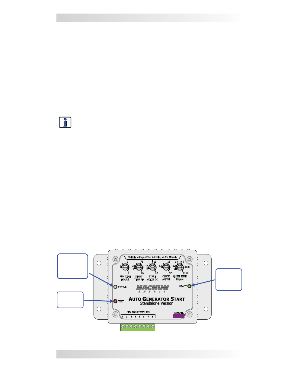
The front of the controller (Figure 4-1) provides a pushbutton to test the
AGS system operation, and two LED indicators for viewing system operation.
4.1.1 TEST
Switch
The TEST switch when pressed and released attempts to turn on the con-
nected generator and allow it to run for at least 30 seconds before turning the
generator off. This start/stop test is used to confi rm that all wiring from the
generator to the AGS is correct and that the GEN TYPE setting is confi gured
correctly for your generator type.
Info: Pushing and releasing the red TEST pushbutton switch enables
the same test as pressing and releasing the momentary TEST position
on the AGS remote switch.
4.1.2
STATUS LED Indicator
Blinking Green – Indicates that the AGS system is initiating a generator
start sequence. This can happen based on two conditions, either: 1) The TEST
switch (on the controller or remote switch) has been pressed and released;
or, 2) The remote switch has been set to the ENABLE position and the START
TEMP °F setting and/or the START VOLTS DC setting has been reached.
Solid Green – Indicates the generator has started successfully and is provid-
ing the run sense voltage to Terminals 2 (+) and 4 (-) of the AGS controller.
Solid Red – This is a fault condition to indicate that the generator has not
provided a correct run sense voltage to Terminals 2 (+) and 4 (-) of the AGS
controller after four start attempts.
4.1.3
READY LED Indicator
Solid Green (normal AGS system indication) – Indicates the AGS control-
ler has power and the remote switch is plugged in correctly.
Blinking Green – Indicates that the AGS controller has power, but the remote
switch is not sensed. This means the remote switch is either not connected,
incorrectly connected, is defective, or has an incorrect or defective cable.
STATUS
Indicator
(green/red)
TEST
Switch
READY
Indicator
(green)
Figure 4-1, Controller Front Panel Controls and Indicators