0 troubleshooting, Troubleshooting 5.0 troubleshooting – Magnum Energy AGS Stand Alone (ME-AGS-S) User Manual
Page 28
25
© 2013 Magnum Energy, Inc.
Troubleshooting
5.0 Troubleshooting
There are two LED (Light Emitting Diode) indicators on the front of the AGS
controller to indicate how the AGS is operating and to help troubleshoot the
AGS system. The STATUS indicator is a bi-color (green or red) LED to indicate
the AGS status. The READY indicator is a green LED to indicate if the AGS has
power and if the remote switch is connected.
The AGS controller will perform a “self test” when power is fi rst applied. The
green READY indicator comes on (solid) and at the same time, the STATUS
indicator blinks green once. If the self-test is correct, test the AGS system
for proper operation by pressing and releasing the AGS switch to the TEST
position. The STATUS indicator begins to blink green and the AGS should start
the generator. After the generator has started, the STATUS indicator should
turn on solid green and the generator should run for approximately 30 seconds
and then shut off. If the generator does not start and stop as expected, refer
to the troubleshooting chart below to help fi nd a solution.
WARNING: Completely unplug the green 8-port friction-fi t termi-
nal block from the
AGS
controller
before servicing the electrical or
generator system to prevent harm to servicing personnel.
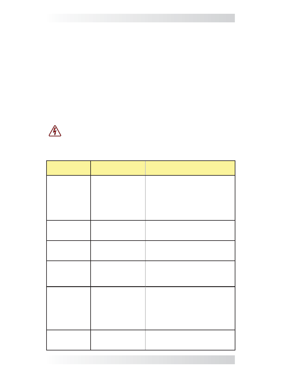
LED
Indication
Symptom
Solutio
n
STATUS is ON
red = Gen Fault
1. Gen won’t start; or
2. Gen won’t run. It
starts, but is stopped
by the AGS (B+ or
run sense voltage not
sensed to Terminal
#2).
Check gen to AGS start wiring; or
check B+ wiring from gen to AGS.
Measure DC voltage from Terminal
2 (+) to Terminal 4 (-), ensure DC
voltage is 10-40 volts only when the
generator is running.
Switch OFF, then ENABLE to reset.
STATUS blinking
green = gen
start initiated
Gen start initiated.
No problem – normal operation.
STATUS is ON
(solid) green =
Gen Run
Gen started OK.
No problem – normal operation.
READY is OFF =
no power con-
nected to the
AGS controller
DC voltage to pins
3 (+) and 4 (-) on
controller missing or
incorrect.
Check fuse, check DC wiring.
READY is
blinking = the
remote switch is
not connected
The remote control
switch is not sensed
or plugged into the
REMOTE port.
1. Check communications cable
connection to the remote and con-
troller, or
2. Try a different 6-conductor tele-
phone cable (see Figure 2-5).
Switch OFF, then ENABLE to reset.
READY is ON
(solid) = power
connected
The remote control
switch is connected
to the REMOTE port.
No problem - normal operation.
Table 6-1, Troubleshooting Guide