Dial flowmeter replacement (506620), Disassembly, Reassembly – Precision Medical PM4351 EasyFlow5 User Manual
Page 16
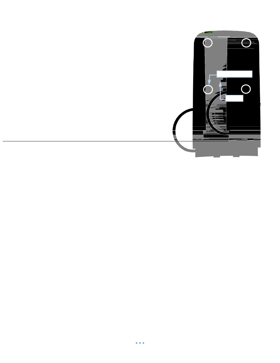
14
Screws (X4)
PCB
Insulating
Paper
Front
Panel
Dial Flowmeter Replacement (506620)
Disassembly
Tools and equipment required:
# Phillips Screwdriver
½” Wrench
Needle Nose Pliers
When handling the PCB, always use ESD Protection.
1. Follow steps all steps for Front Panel Assembly Replacement; Disassembly.
2. Using a Phillips Screwdriver, remove the four Screws securing the PCB to the
Front Panel and set aside.
3. Remove Insulating Paper and set aside.
4. From the top right hand corner of the PCB (as shown) pull the PCB
upward to disengage the Power Switch from the PCB.
5. Position the PCB so that the backside of the Dial Flowmeter is
exposed.
5.1. Keep Tubing inserted thru PCB hole as shown.
6. Disengage Hose Clamp on Tube on back of Dial Flowmeter and slide it up
and off the Barb.
7. Using Needle Nose Pliers, remove the Tube off the Dial Flowmeter Barb.
8. Using a
½” wrench, remove Dial Flowmeter Hex Nut.
9. Remove Dial Flowmeter from the Front Panel.
Reassembly
(Reference Disassembly Photos)
When handling the PCB, always use ESD Protection
1. Insert new Dial Flowmeter from front side of the Front Panel, aligning the
center Stud and Barb with the corresponding openings.
2. Apply Loctite
®
425 to threads of Flowmeter Assembly.
3. While holding Flowmeter Outlet Fitting, tighten Hex Nut.
4. Place Tube onto Flowmeter Barb. Tube should cover entire Barb.
5. Slide Clamp onto Tube at barb of Flowmeter and engage.
5.1. Leave approximatel
y 1/8’’ gap between Clamp and Front Panel.
6. Position the PCB back into place while ensuring terminals for Power Switch are aligned and the Tubing from the Dial
Flowmeter is routed as shown.
7. Press PCB terminal connectors onto Power Switch.
8. Place Insulating Paper over bottom half of PCB, aligning the two (2) top holes with the two (2) lower holes on the
PCB.
9. Using the four (4) #6 pan head Phillips Screws secure the PCB to the Front Panel as shown.
10. Follow all steps for Front Panel Assembly Replacement; Reassembly.