Digital and opto ports chapter 6 – Remote Processing RPC-52 User Manual
Page 18
DIGITAL AND OPTO PORTS
CHAPTER 6
Page 16
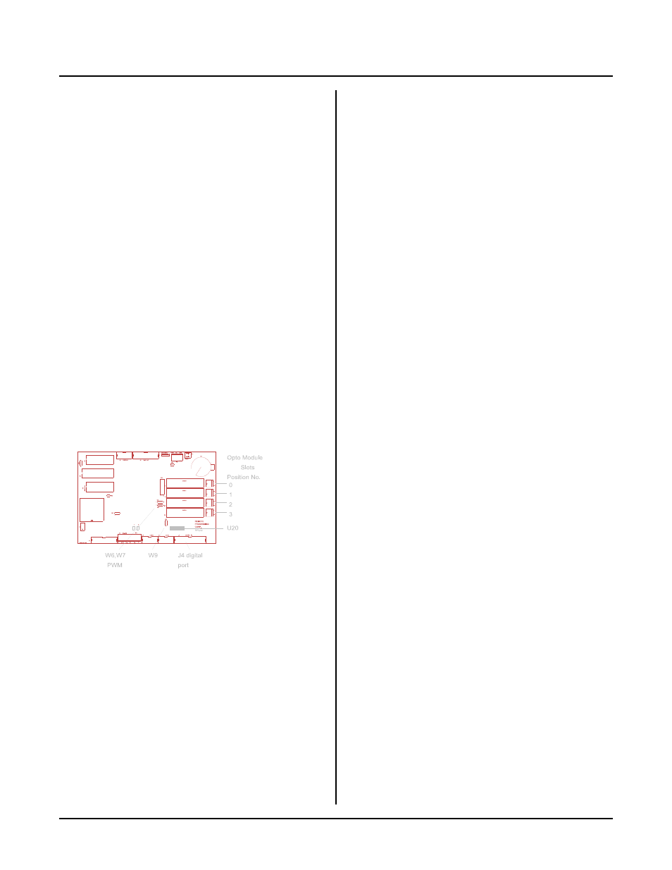
Figure 6-1 Digital I/O
INTRODUCTION
Digital I/ O lines ar e used to inter face with op to-module
racks, switches, low current LED's, and other TTL
devices. The RP C-52 ha s 24 of these lines a vailable
through J4. 8 of these lines are high cur rent outputs,
capable of sinking 75 to 200 ma. Additionally, there are
4 opto-module sockets on the card itself.
On-car d opto-mo dule slots accep t G4 and G 5 series op to
modules. G 4 series opto modules are used to sense the
p r e se n ce o f A C o r D C vo lt a ge s or s w it c h t he m .
Maxim um switching cur rent is 3 amper es.
G5 series are optically isolated analog input or output
modules. The modu les connect to therm ocouples,
RTD' s, load cells, 4-20 ma current loops, and general
purpose voltage inputs. They can also output voltages
and currents. These modules are supported by the
G5MOD command. Input modules return a number
f r om 0 to 2 55 in a m an n er s im i la r to a n A - D .
Conver sion time is 7 milli-seconds.
In addition to the 24 I/O lines from J4, the display port
can be used as digital I/O. Refer to chapter 8 for more
information.
T w o on c ar d op to r ac k sl ot s m a y b e ju m pe r ed fo r P W M
output.
WARNING:
Apply power to the RPC -52 before applying a
voltage to the digital I/O lines to prevent current
from flowing in and damaging devices. If you
cannot apply power to the RPC-52 first, contact
technical support for suggestions appropriate to your
application.
This chapter is divided into two sections. T he first
section is about the on-card opto rack. The second
section refers to the digital I/O port J4.
ON-CARD OPTO RACK
Description
The on-c ard opto r ack accep ts the G4 ser ies opto
modules (manufactured by Opto-22, Grayhill, and
others). These modules can switch AC or DC voltages
from 5 to 240 v olts at 3 amperes. They can also sense
input voltages of the same type and range.
O p to c ha n ne ls 0 a n d 1 c an b e j um p er e d f or P W M
outputs. PW M output is also used to generate analog
output.
The RP C-52 also accepts the G rayhill G5 ser ies. T hese
modules m easure voltage, curr ent, therm ocouple outp ut,
or RTD resistance and return it as a frequency.
Additionally, modules c an output a volta ge or a c urre nt.
RPBASIC-52 suppor ts the G5 series through the
G5MO D comm and.
Installation
G4 and G5 modules are installed in the same manner as
an opto rack. A screw at the top is used to secure the
module to the board. M odules may be installed in any
order and types can be intermixed.
A hole for a standoff nea r the m odules is pro vided to
keep the board from bending during installation or
rem oval.
Input and output lines are fastened by the two position
term inal in front of the opto mo dule. The m odule
number is in each module position and behind the
module. T his module position is used in conjunction
with the L INE statement.
Refer to the appropriate module data sheet for additional
hookup information, if requir ed.
G4 operation
G4 modules are accessed using the LINE command and
function. Line number s are from 0 to 3. To turn on a
module, execute the fo llowing statem ent:
100 LINE 2,ON
To return the status of a line, execute the following:
200 A = LINE(3)
PWM O utput
Opto module positions 0 and 1 may be jumpered for
PWM output. Power up frequency and duty cycle are
set using the C ONF IG PW M statem ent. The duty c ycle
is changed du ring r un time using the PW M statem ent.
See the RPBASIC-52 Softwar e Supplement for
inform ation on these co mma nds. The fr equency is
adjustable from approximately 170 Hz to 40 Khz. The
freque ncy is the sam e for both channels. Duty cyc le is
adjustable with a 1/255 resolution. Each channel is set