Analog i/o chapter 10, Description, Connecting analog i/o – Remote Processing RPC-52 User Manual
Page 28
ANALOG I/O
CHAPTER 10
Page 26
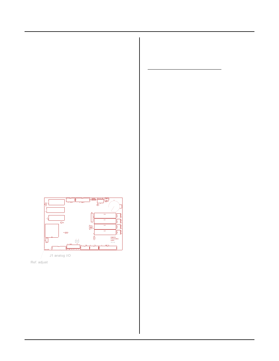
Figure 10-1 Analog I/O
DESCRIPTION
The RP C-52 has 8 single ended a nalog input channels.
These channels can be used to measure voltages from
transducers, 4-20ma current loops, thermistors, etc.
Input voltage range is 0 to 5 volts with 10 bit (1024
count) resolution. In addition to the inputs, there are 2
analog outputs that are shar ed with the PW M positions.
These outputs may be used to control the speed of
motors or provide an analog indication of a level or
position. Output voltage can be varied in 255 steps from
0 to 5 volts.
This chapter begins with basic information on connecting
and using ana log inputs. Later , de scriptions of how to
measure voltages other than 0 to 5 volts, data logging,
and calibr ation are e xplained. Gener ating analog ou tputs
are then discussed.
The analog inputs on this card are above any others used
in the opto module slots. Inputs and outputs discussed
here are not optically isolated.
CONNECTING ANALOG I/O
All analog I/O interfaces through connector J1. An
STB-20 an d CM A-20-24 ribbon ca ble can be use d to
provide screw termin al interfac e. Sc rew te rmina ls
accommodate 12-22 gauge wir ing.
Additional compone nts, such as r esistors and capacitors,
may be conne cted directed to the scre w term inals.
Analog I/O J1 pin out
Use the fo llowing table to c onnect to the ap propr iate
input or output. Pin number s correspond to those on the
STB-20.
Description
J1 pin
Chann el 0 in
1
Analog ground
2
Chann el 1 in
3
Analog ground
4
Chann el 2 in
5
Analog ground
6
Chann el 3 in
7
Analog ground
8
Chann el 4 in
9
Analog ground
10
Chann el 5 in
11
Analog ground
12
Chann el 6 in
13
Analog ground
14
Chann el 7 in
15
Analog ground
16
Analog 0 out
17
Digital ground
18
Analog 1 out
19
Digital ground
20
Grounding
Analog ground is somewhat isolated from digital ground.
While the ground plane is connected between the two,
analog ground is a virtual "island" connected only in one
place to digital ground. To minimize noise pickup, the
sending device should be connected to analog ground.
When both analog and digital grounds come from the
same device, you w ill have to play around with the
grounds to deter mine which sche me prov ides the best
p e r fo r m a nc e fo r y ou r sy s te m .
ACQUIRING ANALOG DATA
Analog data is accessed with the AIN function. The
syntax is:
A = A I N (channel)
This function assigns the analog value of a channel to the
variable ; A in th is case. The value retur ned is alway s in
the 0 to 1023 range because the converter is 10 bits. A 0
corresponds to 0.000V and 1023 corresponds to 4.99V.
To view the result of a conversion in the command
mode, type:
print ain(0)
The result at channel 0 is returned.
The AIN function require s about 1 ms to convert the
data. Additional time is needed to store the data. The
example below takes 255 data samples and stores them
into an array which requires 6 bytes per entry. The
second example takes only two byes per entry, can save
to extended m emor y, b ut requir es a longer time to get a