Thermo Pride Gas/Propane Furnace Premiere Series 2-Stage CHX3 User Manual
Page 17
All installations and services must be performed by qualified service personnel.
11
NOTICE: DO NOT use silicone caulk to seal the pipe sleeve or coupling to the metal air
intake collar on the burner box. Securing the sleeve or coupling to the collar using a screw
is sufficient.
10. Vent connections shall be checked for leakage with the furnace induced draft blower running and
with the vent termination blocked. Use a mild soap and water solution to check for leaks.
11. Vent pipe passing through an unheated space shall be insulated with 1-inch thick, foil-faced
fiberglass insulation, or equivalent, to prevent freezing of condensate within the pipe.
12. No clearance is required from the outer surface of the thermoplastic piping to combustible
materials for fire hazard prevention.
13. Thermo Products does not require screens be installed in the exhaust vent and air intake piping.
However, optional stainless steel screens are available from Thermo Products, should the
homeowner request them.
NOTICE: The CHX3 / CDX3 furnace models may be vented either through the sidewall or the roof.
For sidewall instructions, continue to the following section. For roof venting, refer to Section III G, of
this manual.
E. Direct Venting Through a Sidewall
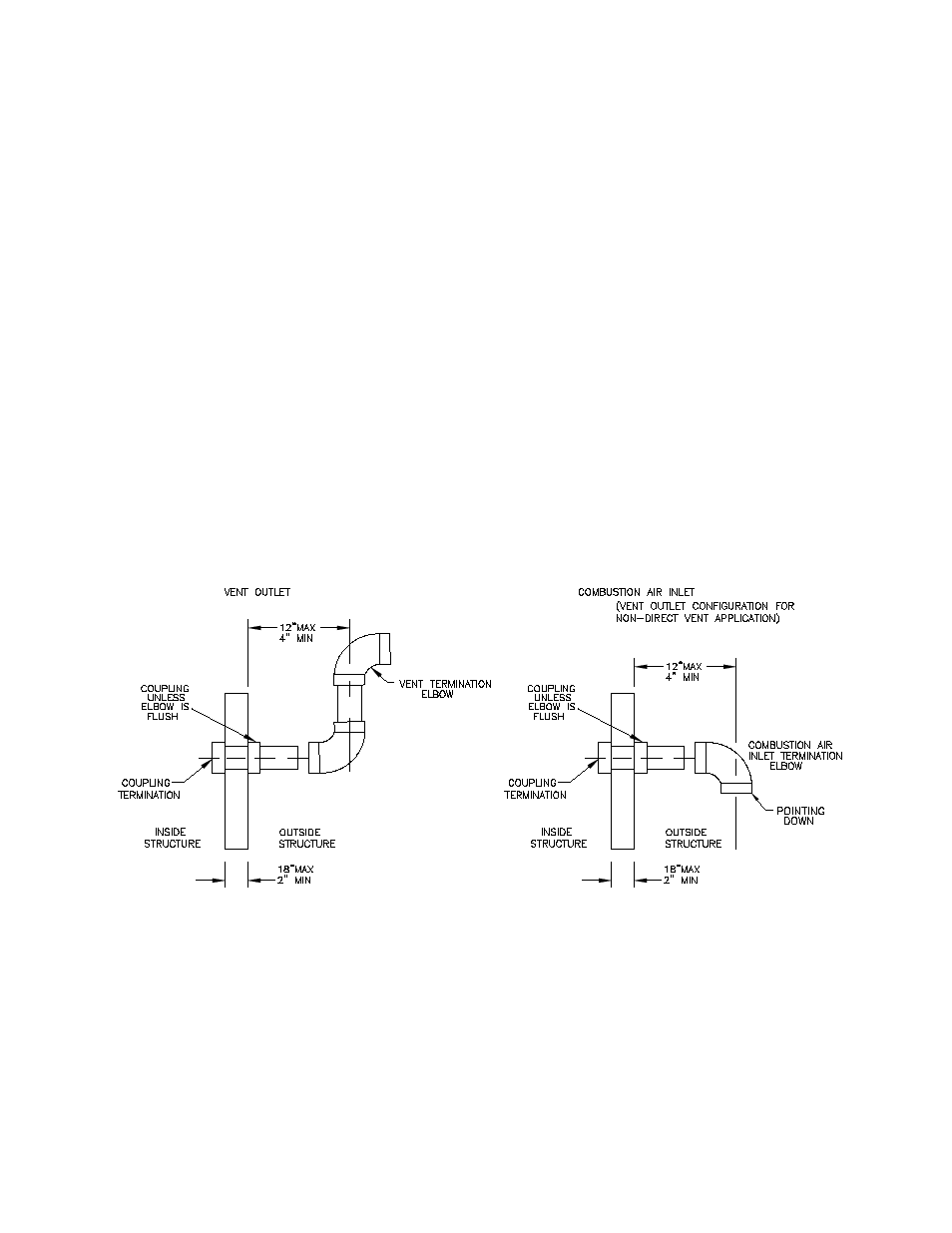
1. Vent and combustion air pipes may pass through a maximum wall thickness of 18 inches. The
minimum wall thickness is 2 inches. Referring to Figure 2, the maximum distance from the outer
wall to the center of the elbow is 12 inches.
Figure 2: Proper Direct Vent Terminations (RH & LH views) and Vent Termination Only w/o
Outside Combustion Air Intake (RH view).
NOTICE: If exterior sidewall building materials are subject to degradation from contact with flue gases or
moisture, a minimum 24-inch diameter shield shall be fabricated from stainless steel or UV-resistant
plastic sheet. The protective shield shall be installed around the vent pipe on the outside wall.
2. The exhaust vent termination elbow shall be installed in accordance with these instructions and
any applicable local codes. Refer to Figures
2 and 3 for typical examples of proper terminations.
a. The exhaust vent termination must be installed in the same atmospheric pressure zone (i.e.
on the same wall) as the air intake termination.