Thermo Pride Gas/Propane Furnace Premiere Series 2-Stage CHX3 User Manual
Page 38
All installations and services must be performed by qualified service personnel.
32
3. THERMOSTAT CONNECTIONS AND ANTICIPATOR SETTING
NOTICE: For two-stage thermostat wire connectors see wire diagram page 59.
For single-stage thermostat with two-stage operation connect W from thermostat to W1 on control. W2
on control board is not used. Thermostat dip switches S7-1 & S7-2 on control board (Fig. 21) will need to
set at the desired setting per (Table 4B). In this configuration the furnace will light and burn on low fire. If
thermostat has not been satisfied in set delay time for second stage the control will step up to high fire
until thermostat is satisfied. The auto setting will allow the control to calculate the delay for second stage
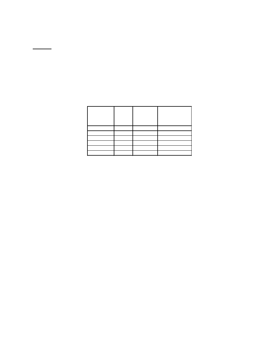
based on demand. The average calculated duty cycle chart below (Table 4A) shows how the control
calculates staging based on demand.
Table 4A
Proper control of the indoor temperature can only be achieved if the thermostat is calibrated to the heating
and/or cooling cycle. A vital consideration of this calibration is related to the thermostat heat anticipator.
The proper thermostat heat anticipator setting is 0.4 AMPS for furnace operation only. To increase length
of cycle, increase setting of heat scale; to decrease length of cycle, decrease setting of heat scale.
Anticipators for the cooling operation are generally pre-set by the thermostat manufacturer and require no
adjustment.
Anticipators for the heating operation are of two types, pre-set and adjustable. Those that are pre-set will
not have an adjustment scale and are generally marked accordingly.
Average
Calculated
Duty Cycle %
Equals
or is less
than
Low to High
Stage Delay
Demand
0
38
12 Min
Light
38
50
10 Min
Light to Average
50
62
7 Min
Average
62
75
5 Min
Average to Heavy
75
88
3 Min
Heavy Light
88
100
1 Min
Heavy